Download
1 / 43
3.01k likes | 7.99k Views
DESIGN OF WASTEWATER TREATMENT PLANT. Clarifier/Sedimentation Tank Design. Design criteria. The following design criteria are generally assumed to design a Primary Settling Tank / Sedimentation. A) GENERAL. B) DIMENSIONS. C) TECHNICAL.

E N D
Design criteria The following design criteria are generally assumed to design a Primary Settling Tank / Sedimentation A) GENERAL
B) DIMENSIONS C) TECHNICAL
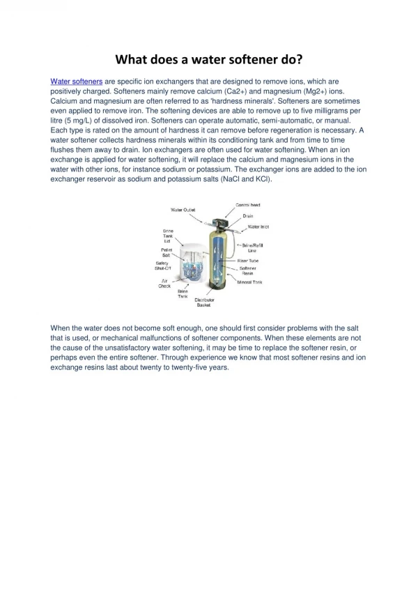
Primarily used in WWT to separate solids from liquids in effluent streams. Types light Clarifiers Criteria for sizing clarifier (settling tank) Overflow rate (surface loading rate) Tank depth at the side wall Detention time Scour velocity
Criteria For Sizing Clarifier (Settling Tank) -Overflow Rate (Surface Settling Rate)- Definition: The average daily flow rate divided by the surface area of the tank. Clarifiers Average daily flowrate (m3/day) overflow rate @ surface settling rate (m3/m2d) Total surface area of the tank (m2)
Criteria For Sizing Clarifier (Settling Tank) -Depth Of Tank- The water depth at the side wall measuring from the tank bottom to the top of the overflow weir. Depth of tank Effluent weir Exclude the additional depth resulting from slightly sloping bottom that is provided in both circular and rectangular clarifiers. Influent Influent H Occupied with sludge Effluent weir loading (typical= 250 m3/m.d) is equal to quantity of WW flowing divided by the total weir length, Lw Average daily flowrate (m3/day) Total weir length (m)
Criteria For Sizing Clarifier (Settling Tank) -Detention Time- length of time a particle or a unit volume of WW remains in a reactor Detention time Tank volume (m3) Detention time = (day) Average daily flowrate (m3/day)
Criteria for sizing clarifier (settling tank) -Scour velocity horizontal velocity through the tank to avoid resuspension of settled particles Scour Velocity Where: VH = horizontal velocity that will just produce scour (m/s) k = cohesion constant that depends on type of material being scoured (unitless) s=specific gravity of particles g=acceleration due to gravity (9.81 m/s2) d=diameter of particles f=Darcy-Weisbach friction factor (unitless)
Design Criteria • Surface Organic Loading Rate • Depth • Detention Time • Geometry (L/B ratio)
Surface Organic Loading Rate • Related with algae activity and balance between oxygen production and consumption.
Depth • Based on volume, V and the required area, A , the depth (H) of pond = V/A. • H = 1.5 to 2.0 m
Detention time • In primary detention time,t usually vary from 15 to 45 days.
If K = 0.35d-1θ=1.085 If K = 0.30d-1θ=1.05
AEROBIC POND DESIGN • Design Criteria • Detention time, t = 5 to 10 days • Depth, H = 2.5 to 4.0 m • Oxygen Requirement • Power Requirement