Download
1 / 26
380 likes | 985 Views
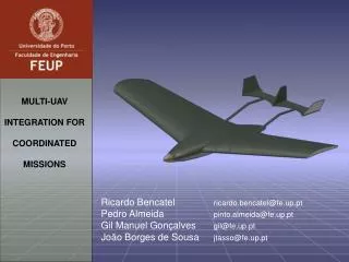
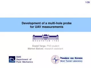
Development of a multi-hole probe for UAV measurements. Árpád Varga , PhD student Márton Balczó , research assistant. 5-hole probes. Why a 5-hole probe? 3D time resolved velocity vector measurement in a 40 -deg cone low-cost, robust. a : pitch b : yaw. pressure coefficients.

E N D
Development of a multi-hole probe for UAV measurements Árpád Varga, PhD student Márton Balczó, research assistant
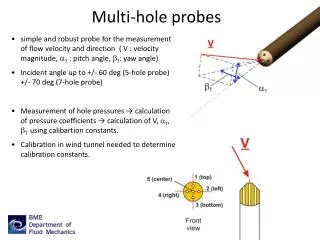
5-hole probes • Why a 5-hole probe? • 3D time resolved velocity vector measurement in a 40-deg cone • low-cost, robust a: pitch b: yaw
pressure coefficients angle coefficients • q: dynamic pressure dyn. pressure correction coeff. • ∆p: corrected average pressure from the 4 side holes: to static pressure port
During measurement: • measure pressures, • determine normalized coefficients, • calculate q, a, b using polinomial surfaces Principle - directional calibration • During calibration: • set velocity and flow angles • measure pressures • determine normalized coefficients • fit polinomialsurfaces toq, a, b.
Rapid prototyping Manufacturing - spatial resolution • Traditional • soldering of copper tubes OD= 4mm, ID 0.5mm, L = 130mm • current method with 50mm resolution too rough
Sensors, digital communication • Sensortechnics HCLA miniature temperature compensated, amplified sensors • communication during lab testing: 400 kHz I2C bus using a NI 8452I2C-USB interface: 0.4 ms readout time for 6 sensors: approx 800 Hz sampling rate
Wind tunnel used for calibration • Blower type open test section wind tunnel • 350 mm cross section, 0,8%-os turbulence-intensity, max 24 m/s
How to adjust calibration rig’s axis to the wind direction • adjust angle in small steps • rotate probe around axis 0- 180 deg at each angle • pressure coefficient change to be minimized
Directional calibration • Control measurements in 600 random points: • angular error < 0.4° • q error < 2.5 Pa
Dynamic calibration Ref. sensor: piezoresistive microphone up to 10kHz • Do frequency scan 1-500 Hz • Determine amplitude ratio and phase shift
Reconstruction of the signal in time domain 45Hz sine 180Hz sine
Signal reconstruction – noise measurement FFT Signal Standard deviation [Pa] Max. deviation [Pa] reference 0.2 1.2 measured 0.3 1.9 reconstructed 1.2 6.0
Conclusions • 5HP probe developed and calibrated • low cost, digital sensors • zero alignment during calibration should be taken care of • temporal resolution is subject of damping from the tubing, with optimization and recompensation, up to 250 Hz can be achieved.