Download
1 / 13
140 likes | 554 Views
G.8032 for Ethernet Networks Ethernet Ring Protection. Yaacov Weingarten Nokia Siemens Networks. Agenda. Why Rings? Status of G.8032 Multiple instances – bandwidth efficiency Inter-connected rings Operator commands. Why Rings?.

E N D
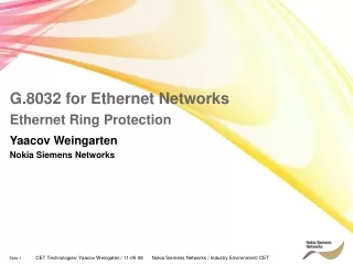
G.8032 for Ethernet NetworksEthernet Ring Protection Yaacov Weingarten Nokia Siemens Networks
Agenda • Why Rings? • Status of G.8032 • Multiple instances – bandwidth efficiency • Inter-connected rings • Operator commands
Why Rings? • Considered the simplest redundant topologies and are often encountered in Metropolitan Ethernet Networks (Metro) to minimize optical fiber usage. • Effective means of aggregating DSLAMs or small Ethernet switches in multi-tenant or multi-dwelling environments in Metro access networks
Status of G.8032 • Recommendation was consented within working group in Feb 2008 • Sent for Last Call comments during month of April • Four companies submitted comments • Technical comments were addressed during interim meeting, 30 Apr – all resolved to satisfaction of commenting companies • Additional resolution (of editorials) within two weeks • Begun work on next revision of the Recommendation. New revision will address: • Multiple Instances • Inter-connected ring topologies and protection • Operator commands – e.g. Manual switch, Forced switch
Multiple Instances – bandwidth efficiency • Ability to configure different logical rings that are protected, each with its own RPL (and RPL Owner). • Allows greater utilization of all the links in the ring, possibly in different logical rings • Each ring is addressed separately in R-APS messages • Using VID or different MAC address (in SA)
Interconnected Rings – General Objectives • Only “reasonable” carrier topologies (that would be configured in actual operator/service provider domains) should be addressed. • The rules defining the Interconnected ring topologies supported are expressed in following slides. • Ring interconnection should not require changes to the single ring protection mechanism. • Although there may be a need to add features to the APS protocol, the basic messages and interactions should not be affected. • Nodes that are not at the ends of shared links should not need special provisioning to support shared links in the ring • When a shared link fails, it is necessary to prevent the formation of a super loop, as may be the case if both rings protect at the same time.
Interconnected Rings – General Guidelines • Shared link may act as the RPL for only one of the rings that share the link • A signal failure on a non-shared link (when the ring is in idle state) should only trigger protection switching within the ring where the link failed, the other interconnected rings should be agnostic to this event
ERP1 ERP2 ERP3 ERP1 ERP2 ERP3 ERP2 ERP1 ERP3 Interconnected Rings – Topology rules • General consensus at ITU discussions to set principles of interconnected ring topologies that will be supported • Interconnected rings may share more than one shared link • A node that is common to different rings may be connected by more than one shared link • A shared link may be shared by more than two rings
ERP1 ERP2 ERP3 ERP4 Shared node Ring A Ring B Shared node Interconnected Rings – Topology Limitations • Interconnected rings shall not form a ring of rings • Two rings shall not be connected by two shared nodes if the link between these nodes is not shared (when two links exist between the two shared nodes) • Two rings shall not be connected by any two shared links if these links are not connected to the same shared node Non shared link Non shared link
Interconnected Rings – Priority-based protection Nokia Siemens Networks proposes to assign a priority to each RPL, through configuration When Shared link fails – only RPL with highest priority protects ring, thereby preventing formation of super loop
Operator commands – Manual/Forced Switch • Operator has need to intervene into current flow control of the ring • Updating node software • Switching hardware – switch out/in of new nodes or links • Periodic maintenance • Support for commands to the ring – Manual Switch or Forced Switch • Need to establish relative priority between commands and Signal Fault situations • Switch mechanism and recovery • Treat special cases – sequential requests, simultaneous requests • General consensus reached at last interim meeting • Forced Switch > higher than Signal Failure > higher than Manual Switch • Simultaneous requests – Manual Switch cancel out, Forced Switch co-exist
Manual Switch behavior RPL A B C D E G F Idle 1 Manual Switch 2 3 MS MS MS MS MS MS MS MS Flush 4 Flush Flush Flush Flush Flush Flush Manual Switch state 5 Clear 6 7 NR NR NR NR NR NR NR NR 8 NR RB NR RB NRRB NRRB NRRB NRRB NRRB NRRB Flush Flush Flush Flush Flush Flush Flush Idle 9 NRRB NRRB NRRB NRRB NR RB NR RB NRRB NR RB