Download
1 / 79
790 likes | 951 Views
This chapter explores how the x86 architecture manages interrupts using the interrupt vector table and routines. It outlines the distinctions between interrupts and CALL instructions, differentiates hardware from software interrupts, and examines interrupt service routines (ISRs). Additionally, it details the 8259 programmable interrupt controller and how control words are programmed. Students will learn the operational mechanics of the x86 interrupts, memory allocation for ISRs, and the implications of hardware interrupts, particularly through the INTR and NMI pins.

E N D
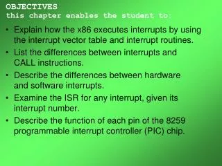
OBJECTIVESthis chapter enables the student to: • Explain how the x86 executes interrupts by using the interrupt vector table and interrupt routines. • List the differences between interrupts andCALL instructions. • Describe the differences between hardwareand software interrupts. • Examine the ISR for any interrupt, given itsinterrupt number. • Describe the function of each pin of the 8259 programmable interrupt controller (PIC) chip.
OBJECTIVESthis chapter enables the student to: (cont) • Explain the purpose of each of the four control words of the 8259 and demonstrate how theyare programmed. • Examine the interrupts in x86 PCs.
14.1: 8088/86 INTERRUPTS • An interrupt is an external event that informs the CPU that a device needs its service. • In 8088/86 there are a total of 256 interrupts. • INT 00, INT 01, ..., INT FF (sometimes called TYPEs). • When an interrupt is executed the processor: • Saves the flag register (FR), instruction pointer (IP),and code segment register (CS) on the stack,. • Goes to a fixed memory location. • In x86, always four times the value of the interrupt number.
14.1: 8088/86 INTERRUPTSinterrupt service routine (ISR) When an interrupt is invoked it is asked to run a program to performa certain service. There must be a program associated with every interrupt . This program is commonly referred to as an interrupt service routine (ISR), and also called the interrupt handler. When an interrupt is invoked, the CPU runs the interrupt service routine.
14.1: 8088/86 INTERRUPTS interrupt service routine (ISR) • For every interrupt thereare allocated four bytesof memory in the interrupt vector table. • Two bytes for the IP. • Two for the CS of the ISR. • These locations provide the addresses of the interruptservice routine for which the interrupt was invoked. • The lowest 1024 bytes of memory space are set aside for the interrupt vector table.
14.1: 8088/86 INTERRUPTS differences between INT and CALL • What is the difference between… • INT instruction - which saves the CS:IP of the following instruction and jumps indirectly to the subroutine associated with the interrupt. • A CALL FAR instruction, which also saves CS:IPand jumps to the desired subroutine (procedure)?
14.1: 8088/86 INTERRUPTS differences between INT and CALL • A "CALL FAR " instruction… • can jump to any location within the 1-megabyte address range of the 8088/86 CPU. • The "INT nn" goes to a fixed memory location in the interrupt vector table to get the address of the interrupt service routine. • is used in the program instructions, but an externally activated hardware interrupt can come in any time, requesting CPU attention. • cannot be masked (disabled), but "INT nn" belonging to externally activated hardware interrupts can be masked. • auto-saves only CS:IP of the next instruction on the stack. • "INT nn" saves FR (flag register) also.
14.1: 8088/86 INTERRUPTS differences between INT and CALL • "INT nn" is a 2-byte instruction where the first byte is for the opcode & the second the interrupt number. • A maximum of 256 (INT 00 INT FFH) interrupts. • Some are used for software interrupts; some for hardware.
14.1: 8088/86 INTERRUPTS categories of interrupts • Three x86 pins are associated with hardware interrupts... • INTR (interrupt request) • NMI (nonmaskable interrupt) • INTA (interrupt acknowledge) • INTR is a CPU input signal, which can be masked (ignored) & unmasked through use CLI and STI. • NMI, also an input signal into the CPU, cannot be masked and unmasked using CLI & STI. • For this reason, it is called a nonmaskable interrupt.
14.1: 8088/86 INTERRUPTS hardware interrupts • INTR and NMI are activated externally by putting5V on the x86 microprocessor NMI & INTR pins. • On activation of either interrupt, x86: • Finishes the instruction it is executing. • Pushes FR & CS:IP of the next instruction onto the stack. • Jumps to a fixed location in the interrupt vector table and fetches the CS:IP for the interrupt service routine (ISR) associated with that interrupt. • At the end of the ISR, IRET causes the CPU to get (pop) back its original FR and CS:IP from the stack. • Forcing the CPU to continue at the instructionwhere it left off when the interrupt came in.
14.1: 8088/86 INTERRUPTS hardware interrupts • Intel has embedded "INT 02" in x86, only for NMI. • Whenthe NMI pin is activated, the CPU location 00008to get the address (CS:IP) of the ISR. • Memory locations 00008, 00009, 0000A, and 0000Bcontain the 4 bytes of CS:IP of the ISR belonging to NMI. • There is no specific location in the vector table assigned to INTR. • Allowed to use any "INT nn" not previously assigned. • The 8259 programmable interrupt controller (PIC) chip can be connected to INTR to expand the number of hardware interrupts to 64.
14.1: 8088/86 INTERRUPTS software interrupts • An ISR called as a result of execution of an x86 instruction such as "INT nn“ is referred to as a software interrupt. • As it was invoked from software, not external hardware. • DOS "INT 21H" function calls,and video interrupts "INT 10H". • Can be invoked in code like a CALL or other x86 instruction • Some of the interrupts are associated with predefined functions.
14.1: 8088/86 INTERRUPTS software interrupts Interrupts INT 05 to INTFF can be used for either software or hardware interrupts. INT 00 to INT 04 have predefined functions. INT 00 (divide error) INT 01 (single step) INT 03 (breakpoint) INT 04 (signed number overflow) Figure 14-1 Intel's List of Designated Interrupts for the 8088/86
14.1: 8088/86 INTERRUPTS interrupts and the flag register • Two flag register bits are associated with interrupt: • D9, or IF (interrupt enable flag) • D8, or TF (trap or single step flag). • OF (overflow flag) can be used by the interrupt.
14.1: 8088/86 INTERRUPTS processing interrupts • When 8088/86 processes any interrupt: • 1. The flag register (FR) is pushed onto the stack &SP is decremented by 2, as FR is a 2-byte register. • 2. The IF (interrupt enable flag) & TF (trap flag) areboth cleared. (IF = 0 and TF = 0). • 3. The current CS is pushed onto the stack andSP is decremented by 2. • 4. The current IP is pushed onto the stack and SPis decremented by 2.
14.1: 8088/86 INTERRUPTS processing interrupts • When 8088/86 processes any interrupt: • 5. The INT number (type) is multiplied by 4 to get the physical address of the location within the vector tableto fetch the CS and IP of the interrupt service routine. • 6. From the new CS:IP, the CPU starts to fetch and execute instructions belonging to the ISR program. • 7. The last instruction of the interrupt service routine must be IRET, to get IP, CS, and FR back from the stack and make the CPU run the code where it left off.
14.1: 8088/86 INTERRUPTS software interrupts A conditional or exception interrupt. Invoked by the processor when there are conditions (exceptions) the CPU is unable to handle. INT 00 invokes by when there is an attempt to divide a number by zero. INT 00 is also invoked if the quotientis too large to fit into the assigned register when executing a DIV. INT 00 to INT 04 have predefined functions. INT 00 (divide error)
14.1: 8088/86 INTERRUPTS software interrupts Intel designated INT 01 specificallyfor implementation of single-stepping instructions for program tracing. The trap flag (TF), D8 of the flag register, must be set to 1. After execution of each instruction, 8088/86 jumps to physical location 00004 to fetch CS:IP of the interrupt service routine. INT 00 to INT 04 have predefined functions. INT 01 (single step)
14.1: 8088/86 INTERRUPTS hardware interrupts All Intel x86 processors have a pin designated NMI, an active-high input, and has reserved INT 02 for NMI. When the NMI pin is activated by a high (5V) signal, the CPU jumps to physical memory location 00008 to fetch the CS:IP of the ISR routine associated with NMI. INT 00 to INT 04 have predefined functions. INT 02 (nonmaskable interrupt)
14.1: 8088/86 INTERRUPTS software interrupts Intel has set aside INT 03 for the implementation of breakpoints in software engineering. A breakpoint is used to examine CPU and memory after the execution of a group of instructions. INT 3 is the fact is a 1-byte instruction. INT 00 to INT 04 have predefined functions. INT 03 (breakpoint)
14.1: 8088/86 INTERRUPTS software interrupts Invoked by signed number overflow,& associated with the INTO (interrupt on overflow) instruction. If instruction INTO is placed after a signed number arithmetic or logic operation such as IMUL or ADD, the CPU will activate INT 04 if OF = 1. If OF = 0, INTO is is bypassed, acting as a NOP (no operation) instruction. INT 00 to INT 04 have predefined functions. INT 04 (signed number overflow)
14.2: x86 PC AND INTERRUPT ASSIGNMENT • Of 256 possible interrupts in the x86… • Some are used by the PC peripheral hardware. (BIOS) • Some are used by the Microsoft operating system. • The rest are available for programmers of software applications.
14.2: x86 PC AND INTERRUPT ASSIGNMENT See the entire interrupt list on page 375 of your textbook.
14.2: x86 PC AND INTERRUPT ASSIGNMENT examining the interrupt vector table Using DEBUG's dump command to examine the interrupt vector table of a x86 PC, regardless of CPU it contained.
14.2: x86 PC AND INTERRUPT ASSIGNMENT examining the interrupt vector table • From the CS:IP address of the ISR, it is possibleto determine which source provides the service. • DOS or BIOS.
14.2: x86 PC AND INTERRUPT ASSIGNMENT analyzing an x86 interrupt service routine • The interrupt 12H service is available on any PC with an x86 microprocessor. • The job of INT 12H is to copy the value of the data area used by BIOS from memory locations 00413H and 00414H into AX and return. • A function of the BIOS POST is to test & count totalK bytes of installed conventional RAM, and write itin memory locations 00413H and 00414H • After INT 12H, AX will then contain the totalK bytes of conventional RAM memory.
14.2: x86 PC AND INTERRUPT ASSIGNMENT analyzing an x86 interrupt service routine Interrupt Service Routine in theIBM PC Technical Reference:
14.2: x86 PC AND INTERRUPT ASSIGNMENT INT 12H: checking the RAM size on the PC
14.2: x86 PC AND INTERRUPT ASSIGNMENT INT 12H: checking the RAM size on the PC
Figure 14-3 8259A Programmable Interrupt Controller 14.3: 8259 INTERRUPT CONTROLLER • x86 has only pins INTR& INTA for interrupts.
14.3: 8259 INTERRUPT CONTROLLER The Intel 8259 programmable interrupt controller (PIC) makes expansionof the number of hardware interrupts much easier. Figure 14-4 Partial Block Diagram of the 8259A
14.3: 8259 INTERRUPT CONTROLLERpins • CAS0, CAS1, and CAS2 - can be used to setup several 8259 chips to expand the numberof hardware interrupts to 64. • By cascading 8259 chips in a master/slave configuration. • To use 8259 in slave mode, the chip must be programmedand CAS0 to CAS2 are ignored. • SP/EN, slave programming/enable - in buffered mode, an output signal from 8259 to activate the transceiver (EN). • In nonbuffered mode, an input signal into the 8259. • SP = 1 for the master and SP = 0 for the slave.
14.3: 8259 INTERRUPT CONTROLLERpins • INT - an output connected to INTR of the x86. • INTA - input to the 8259 from INTA of the x86. • IR0 to IR7, interrupt request - hardware interrupts. • When a HIGH is put on any interrupt from IR0 to IR7,8088/86 will jump to a vector location. • For each IR there exists a physical memory locationin the interrupt vector table. • The x86 has 256 hardware or software interrupts.(INT 00–INT FF)
Figure 14-3 8259A Programmable Interrupt Controller 14.3: 8259 INTERRUPT CONTROLLERcontrol words and ports • Four control wordsassociated with the 8259: • ICW1 (initialization command word); ICW2; ICW3; ICW4. • There is only one address line A0 to communicate with the chip.
14.3: 8259 INTERRUPT CONTROLLERcontrol words and ports Table 14-3 and Example 14-7 show the values that A0 and CS must take to initialize the 8259.
14.3: 8259 INTERRUPT CONTROLLERcontrol words and ports • ICW1, initialization command word 1 - functions to make a distinction between ICW2, ICW3, and ICW4 when they are sent to the same address of 8259. • D0, LSB of ICW1, tells 8259 if it should look for ICW4or not. • If D1 is high, it knows the system is configured in slave mode should not expect any ICW3 in the initialization sequence. • Initialization must always start with ICW1, followed by ICW2, and finally the last one, if needed; there is no jumping ahead.
14.3: 8259 INTERRUPT CONTROLLERcontrol words and ports • ICW1, initialization command word 1. D2 is always set low (= 0) for x86. D3 chooses between level triggering or edge triggering of the input signals IR0–IR7. D4 must always be high. D5, D6, and D7 are all low for x86 processors. Figure 14-5 ICW Formats (ICW1 and ICW2)for the 8259
14.3: 8259 INTERRUPT CONTROLLERcontrol words and ports • ICW2, initialization command word 2 - assigns interrupt numbers to IR0–IR7. • The 8-bit INT type number assigned to the corresponding IR0 through IR7 is formed by the lower three bits D3–D7. (T3 through T7) • Lower three bits, D0, D1, and D2, vary from 000 to 111.
14.3: 8259 INTERRUPT CONTROLLERcontrol words and ports • ICW2, initialization command word 2. D3–D7 can only be programmed according to the assignment ofthe INT type. The lower bits are provided by 8259, depending on which interrupt of IR0 to IR7is activated. Figure 14-5 ICW Formats (ICW1 and ICW2)for the 8259
14.3: 8259 INTERRUPT CONTROLLERcontrol words and ports • ICW3, initialization command word 3 - used only when two or more 8259s are cascaded. • A single 8259 can be connected to eight slave 8259s. • In cascade mode, there are separate ICW3 wordsfor the master and the slave. • ICW4, initialization command word 4 - D0 indicates the processor mode. (PM) • D0 equals 1 for the 8088/86 and 0 for the 8080/8085. • D1 is AEOI (automatic end of interrupt), is high it eliminates the need for an EOI instruction to be present before the IRET (interrupt return) instruction in the interrupt service routine.
14.3: 8259 INTERRUPT CONTROLLERcontrol words and ports The 8259 can work in either buffered or nonbuffered mode. Figure 14-6a & b ICW Formats (ICW3 and CW4)for the 8259 - Master & Slave
14.3: 8259 INTERRUPT CONTROLLERcontrol words and ports SFNM, special fully nested mode must be used when8259 is in master mode, Figure 14-6a & b ICW Formats (ICW3 and CW4)for the 8259 - Master & Slave
14.3: 8259 INTERRUPT CONTROLLERmasking/prioritization IR0–IR7 interrupts What happens if more than one of interruptsIR0–IR7 is activated at the same time? Can we mask any of the interrupts? What about responding to another interruptwhile an interrupt is being serviced?
There are three operation command words:OCW1, OCW2, OCW3. 14.3: 8259 INTERRUPT CONTROLLERoperation command word OCW • After ICW1, ICW2, and ICW4 have been issued to initialize the 8259, 8088/86 is ready to receive hardware interrupts through 8259's IR0–IR7 pins. • After the process of initialization, the operation command word, OCW, can be sent to mask any of IR0–IR7, or change the priority assigned to each IR.
14.3: 8259 INTERRUPT CONTROLLERoperation command word OCW • With the help of OCWs, a programmer can dynamically change the priority associatedwith each of IR0–IR7, or mask any of them. • Example 14-9 shows how OCWs are sent to the 8259.
14.3: 8259 INTERRUPT CONTROLLERoperation command word OCW Three registers ofnote in the 8259: ISR(in-serviceregister) IRR(interruptrequest register) IMR(interruptmask register) Figure 14-4 Partial Block Diagram of the 8259A
14.3: 8259 INTERRUPT CONTROLLERoperation command word 1 OCW1 OCW1 is used to mask any of IR0–IR7. Logic 1 is for masking. (disabling) Logic 0 is for unmasking. (enabling) Figure 14-7 OCW Format for 8259A
14.3: 8259 INTERRUPT CONTROLLERoperation command word 1 OCW1 Figure 14-7 OCW Format for 8259A
14.3: 8259 INTERRUPT CONTROLLERoperation command word 2 OCW2 • OCW2 - used to assign a specific priority to the IRs. • Fully nested default mode - assigns the highestpriority to IR0 and the lowest to IR7. • 8259 can be programmed to change the defaultmode to assign the highest priority to any IR. • Specific rotation mode - 8259 can be programmed to make rotation follow a specific sequence rather thanIR0 to IR7. • The IR served will be stamped as the lowest priority, and willnot be served until every other request has had a chance.