Download
1 / 37
370 likes | 545 Views
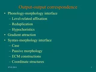
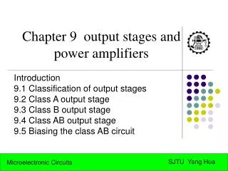
Chapter 9 Output Stages And Power Amplifiers Low Output Resistance – no loss of gain Small-Signal Not applicable Total-Harmonic Distortion (fraction of %) Efficiency Temperature Requirements.

E N D
Chapter 9 • Output Stages And Power Amplifiers • Low Output Resistance – no loss of gain • Small-Signal Not applicable • Total-Harmonic Distortion (fraction of %) • Efficiency • Temperature Requirements
Collector current waveforms for transistors operating in (a) class A, (b) class B, (c) class AB, and (d) class C amplifier stages.
Class A Transfer Characteristics An emitter follower (Q1) biased with a constant current I supplied by transistor Q2. Transfer characteristic of the emitter follower. This linear characteristic is obtained by neglecting the change in vBE1 with iL. The maximum positive output is determined by the saturation of Q1. In the negative direction, the limit of the linear region is determined either by Q1turning off or by Q2saturating, depending on the values of I and RL.
Class A Transfer Characteristics
Class A Transfer Characteristics
Class A Transfer Characteristics Exercises D9.1 and D9.2
Class A Signal Waveforms
Class A Power Dissipation
Class A Power Conversion Efficiency
Class A Exercise 9.4
Biasing the Class B Output • No DC current is used to bias this configuration. • Activated when the input voltage is greater than the Vbe for the transistors. • npn Transistor operates when positive, pnp when negative. • At a zero input voltage, we get no output voltage.
Class A Power Conversion Efficiency CLASS A Many class A amplifiers use the same transistor(s) for both halves of the audio waveform. In this configuration, the output transistor(s) always has current flowing through it, even if it has no audio signal (the output transistors never 'turn off'). The current flowing through it is D.C. A pure class 'A' amplifier is very inefficient and generally runs very hot even when there is no audio output. The current flowing through the output transistor(s) (with no audio signal) may be as much as the current which will be driven through the speaker load at FULL audio output power. Many people believe class 'A' amps to sound better than other configurations (and this may have been true at some point in time) but a well designed amplifier won't have any 'sound' and even the most critical 'ear' would be hard-pressed to tell one design from another. NOTE: Some class A amplifiers use complimentary (separate transistors for positive and negative halves of the waveform) transistors for their output stage.
Class B Circuit Operation CLASS 'B' A class 'B' amplifier uses complimentary transistors for each half of the waveform. A true class 'B' amplifier is NOT generally used for audio. In a class 'B' amplifier, there is a small part of the waveform which will be distorted. You should remember that it takes approximately .6 volts (measured from base to emitter) to get a bipolar transistor to start conducting. In a pure class 'B' amplifier, the output transistors are not "biased" to an 'on' state of operation. This means that the the part of the waveform which falls within this .6 volt window will not be reproduced accurately. The output transistors for each half of the waveform (positive and negative) will each have a .6 volt area in which they will not be conducting. The distorted part of the waveform is called 'crossover' or 'notch' distortion. Remember that distortion is any unwanted variation in a signal (compared to the original signal). The diagram below shows what crossover distortion looks like. Class B output stage.
Class B Circuit Operation Transfer characteristic for the class B output stage in Fig. 9.5.
Operation When the input voltage rises to be large enough to overcome the Vbe, it will begin to cause an output voltage to appear. This occurs because Qn begins to act like an emitter follower and Qp shuts off. The input will be followed on the emitter until the transistor reaches saturation. The maximum input voltage is equal to the following: The same thing will begin to happen if the input voltage is negative by more than the Veb of the transistor. This causes the Qp to act like an emitter follower and Qn turns off. This will continue to behave this way until saturation occurs at a minimum input voltage of:
Emitter Follower Configuration (Chapter 4) Rs will be small for most configurations, so the vb/vs will be a little less than unity. The same is true for re, so vo/vb will be a little less than unity making our vo/vs a little less than unity. Characteristics of the Emitter Follower: • High Input Resistance • Low Output Resistance • Near Unity Gain
Push-Pull Nature of Class B • Push: The npn transistor will push the current to ground when the input is positive. • Pull: The pnp transistor will pull the current from the ground when the input is negative.
Crossover Distortion The Crossover Distortion is due to the dead band of input voltages from -.5V to .5V. This causes the Class B output stage to be a bad audio amplifier. For large input signals, the crossover distortion is limited, but at small input signals, it is most pronounced.
Graph of Crossover Distortion Illustrating how the dead band in the class B transfer characteristic results in crossover distortion.
Power Efficiency Load Power: Since each transistor is only conducting for one-half of the time, the power drawn from each source will be the same. This efficiency will be at a max when Vop is at a max. Since Vop cannot exceed Vcc, the maximum efficiency will occur at pi/4. This will be approximately 78.5%, much greater than the 25% for Class A.
Class AB Circuit Operation
Class AB Output Resistance
Class AB Exercise 9.6
Class AB Exercise 9.6
Class AB Exercise 9.6
Class AB Exercise 9.6
Class AB Exercise 9.6
Class AB Exercise 9.6
Class AB Exercise 9.6
Simplified internal circuit of the LM380 IC power amplifier (Courtesy National Semiconductor Corporation.)
Small-signal analysis of the circuit in Fig. 9.30. The circled numbers indicate the order of the analysis steps.
Structure of a power op amp. The circuit consists of an op amp followed by a class AB buffer similar to that discussed in Section 9.7. The output current capability of the buffer, consisting of Q1, Q2, Q3, and Q4, is further boosted by Q5and Q6.
A class AB amplifier with MOS output transistors and BJT drivers. Resistor R3 is adjusted to provide temperature compensation while R1 is adjusted to yield to the desired value of quiescent current in the output transistors.