Download
1 / 16
530 likes | 1.43k Views
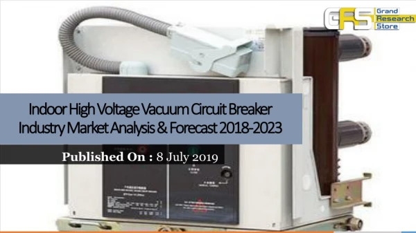
Vacuum circuit-breaker - high duty VD4. Vacuum circuit-breaker high duty 12 kV , 1250 – 2500 A, 4 0 – 63 kA 12 kV, 3150/ 4000 1) A , …63 kA 17.5 kV, 1250 – 2500 A, 40 kA 17.5 kV, 3150/ 4000 1) A, …4 0 kA 36 kV, 1250 – 3150 A, …40 kA 40.5 kV, 1250 – 3150 A, …31. 5 kA.

E N D
Vacuum circuit-breaker high duty • 12kV, 1250 – 2500A,40 – 63 kA • 12kV, 3150/40001)A, …63kA • 17.5kV, 1250 – 2500A,40kA • 17.5 kV, 3150/40001) A,…40 kA • 36kV,1250 – 3150A,…40 kA • 40.5kV, 1250 – 3150 A,…31.5 kA 1) Breaker with fan-cooling
The switchgear complies with the following specifications in according with DIN VDE and relevant IEC publications: • VDE 0670, Teil 1000 and IEC 60694 • DIN VDE 0670,Teil 1 and IEC 62271-100 4) With rated current 2500 A only pole centres 275 mm 5) Breaker with heat-sink 616 mm6) Breaker with heat sink 7) Pole centres 360 mm fixed version Pole centres 280 mm withdraw. version 8) 1000 mm fixed version 1) Test voltage according to DIN VDE 0670, part 1000, list 2 2) When the operating voltage is lower than the rated voltage, the same values apply as for rated voltage 3) 4000 A breaker only with fan cooling
12 kV, 1250-2500 A, 40 kA17.5 kV, 1250-2500 A, 40 kA • p H a b c d e • mm mm mm mm mm mm mm • 210 310 570 424 433 237.5 5991,)2) • 275 310 700 424 433 237.5 5991),2) • 12 kV, 1250-2500 A, 50 kA • p H a b c d e mm mm mm mm mm mm mm • 210 310 6004) 4594) 433 237.5 608 • 275 310 7504) 4594) 433 237.5 608 • 12kV, 3150 A / 4000 A, ...50kA12kV, 1250-4000 A, 63kA17.5 kV, 3150 A / 4000 A1), ...40kA • p H a b c d e mm mm mm mm mm mm mm • 275 310 750 4594) 433 237.5 677.53) • 36 kV, 1250-3150 A, 25-40 kA • 40.5 kV, 1250-3150 A, 25/31.5 kA • p H a b d e mm mm mm mm mm mm • 2805) 328 8955) 6865) 900 1575 • 3606) 328 10006) 5556) 900 1575 Shown: 12 kV, 2500 A, 40 kA 1) Measuring point pole part 4) Max. width or depth 2) Pole with heat-sink 616 mm 5) Version on withdrawable part 6) Fixed version 3) Pole with heat-sink
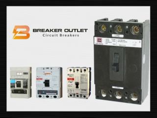
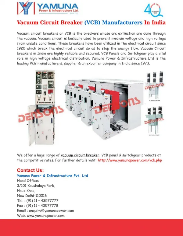
VD4 vacuum circuit-breakers are well suited for switching of: • short-circuit currents • overhead lines under load and no-load conditions • transformers under load and no-load conditions • ripple control systems • capacitors • motors
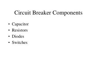
Vacuum interrupter(principle structure ) 1 2 3 1 Stem / Terminal 2 Twist protection 3 Metal bellow 4 Interrupter lid 5 Shield 6 Ceramic insulator 7 Shield 8 Contacts 9 Stem / Terminal 10 Interrupter lid 4 5 6 7 8 9 10 - 6016 E 23-02-06 -
Embedded pole (principle structure) 1 • 1 Upper terminal • 2 Vacuum interrupter • 3 Epoxy resin • 4 Stem • 5 Lower terminal • 6 Movable contact • 7 Contact force spring • 8 Push rod • 9 Fixing point • Connection to operating mechanism 2 3 4 5 6 7 8 9 10
Operating mechanism of vacuum circuit-breaker VD4 - high duty Shown: VD4 1220-50
Vacuum circuit-breaker on withdrawable part intended for indoor installation in air-insulated switchgear systems (front view) Shown: VD4 1231-50
Vacuum circuit-breaker on withdrawable part intended for indoor installation in air-insulated switchgear systems (pole view) Shown: VD4 1220-50
Vacuum circuit-breaker on truck 36 kV, ... 31501) A, ... 402) kA 40.5 kV, ... 31501) A, ... 31.5 kA 1) 3150 A in assembled pole2) 40 kA in assembled pole Shown: VD4 3625-31
1 9 2 3 4 5 6 7 8 12/17.5 kV, 1250 - 2500 A1), 40 kA 1) 2500 A with heat-sink 1 Upper terminal 2 Vacuum interrupter 3 Epoxy resin 4 MC-contact 5 Lower terminal 6 Piston 7 Contact force spring 8 Push rod 9 Mechanism enclosure with spring operating mechanism Shown: Vacuum circuit-breaker, type VD4, in embedded technique 12 kV, 2000 A, 40 kA
1 8 2 3 4 5 6 7 12 kV, 1250 A – 2500 A 50 kA12 kV, 3150 A / 40001) A…50 kA 1) Breaker with fan-cooling 1 Upper terminal 2 Vacuum interrupter 3 Epoxy resin 4 Lower terminal 5 Flexible connection 6 Contact force spring 7 Push rod 8 Mechanism enclosure with spring operating mechanism Shown: Vacuum circuit-breaker, type VD4, in embedded technique 12 kV, 2000 A, 50 kA
12 kV, 1250 – 3150 A / 40001) A, 63 kA 17.5 kV, 1250 – 3150 A / 40001) A, 40 kA 1) Breaker with fan-cooling 1 8 1 Upper terminal 2 Vacuum interrupter 3 Epoxy resin 4 Lower terminal 5 Roller contact 6 Contact force spring 7 Push rod 8 Mechanism enclosure with spring operating mechanism 2 3 4 5 6 7 Shown: Vacuum circuit-breaker, type VD4, with assembled poles
1 2 3 4 5 6 7 36/40.5 kV, ...2500 A, ...31.5 kA with embedded pole 1 Upper terminal 2 Vacuum interrupter 3 Epoxy resin 4 Lower terminal 5 Flexible connection 6 Push rod 7 Mechanism enclosure with spring operating mechanism Shown: Vacuum circuit-breaker, type VD4, in embedded technique 12 kV, 2000 A, 31.5 kA