Download
1 / 32
790 likes | 2.24k Views
Metals: Free Electron Model. Physics 355. +. +. +. +. +. +. +. +. +. +. +. +. +. +. +. +. +. +. +. +. +. +. +. +. +. Free Electron Model. Schematic model of metallic crystal, such as Na, Li, K, etc.

E N D
Metals: Free Electron Model Physics 355
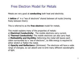
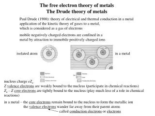
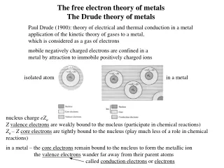
+ + + + + + + + + + + + + + + + + + + + + + + + + Free Electron Model Schematic model of metallic crystal, such as Na, Li, K, etc. The equilibrium positions of the atomic cores are positioned on the crystal lattice and surrounded by a sea of conduction electrons. For Na, the conduction electrons are from the 3s valence electrons of the free atoms. The atomic cores contain 10 electrons in the configuration: 1s22s2p6.
Paul Drude • resistivity ranges from 108 m (Ag) to 1020 m (polystyrene) • Drude (circa 1900) was asking why? He was working prior to the development of quantum mechanics, so he began with a classical model: • positive ion cores within an electron gas that follows Maxwell-Boltzmann statistics • following the kinetic theory of gases- the electrons in the gas move in straight lines and make collisions only with the ion cores – no electron-electron interactions. (1863-1906)
Paul Drude • He envisioned instantaneous collisions in which electrons lose any energy gained from the electric field. • The mean free path was approximately the inter-ionic core spacing. • Model successfully determined the form of Ohm’s law in terms of free electrons and a relation between electrical and thermal conduction, but failed to explain electron heat capacity and the magnetic susceptibility of conduction electrons. (1863-1906)
Ohm’s Law Experimental observation: E
Ohm’s Law: Free Electron Model Conventional current
Ohm’s Law: Free Electron Model Predicted behavior High T: Resistivity limited by lattice thermal motion. Low T: Resistivity limited by lattice defects. The mean free path is actually many times the lattice spacing – due to the wave properties of electrons.
Wiedemann-Franz Law (1853) (Ludwig) Lorenz Number (derived via quantum mechanical treatment)
Free Electron Parameters N/V ×1022 /cm3 kF ×108 /cm vF ×108 cm/s F eV TF ×104 K
Electron Heat Capacity Naïve Thermodynamic Approach: • You could start out by considering the average thermal energy of a free electron at some temperature T. • Then, • And the electronic heat capacity would then be: • However, when we go out and measure, we find the electronic contribution is only around one percent of this.
Electron Heat Capacity • The electron energy levels are mostly filled up to the Fermi energy. • So, only a small fraction of electrons, approximately T/TF, can be excited to higher levels – because there is only about kBT of thermal energy available. • Therefore, • which goes as T2. • …and the heat capacity, • Cel = dU/dT goes as T, which is the correct result. D(F)
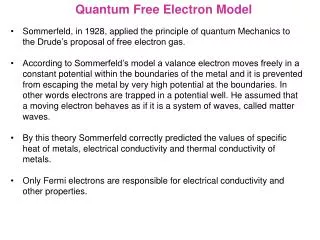
Sommerfeld Constant • The Sommerfeld constant is proportional to the density of states at the Fermi energy, since • Now, we look at this and say, “Obviously!” – because only the electrons very close to the Fermi energy can absorb energy. The Sommerfeld constant is also related to another, rather important, concept in Solid State Physics – effective mass. Effective Mass
+ + + + + + + + + + + + + + + + + + + + + + + + + Effective Mass Electrons are not free! • Electrons interact with • periodic lattice potential • phonons • other electrons
Sommerfeld Constant Observed values come from the linear heat capacity measurements. Calculated values are determined using the conduction electron density and from assuming me = m,
Heavy Fermions Heavy fermions are intermetallic compounds containing non-complete 4f- or 5f-electronic shells. The orbital overlap with ligand atoms in the lattice leads to strong correlation effects in the system of delocalized electrons. As a result, the effective mass of the electrons can increase by orders of magnitude as compared to the free electron mass. Heavy fermion materials exhibit very interesting ground states - such as unconventional superconductivity, small-moment band magnetism and non Fermi liquid behavior.
Heavy Fermions A large value of the Sommerfeld parameter indicates that heavy fermion materials have a high density of states at the Fermi Energy.
Electrical Conduction What's wrong with this?
Hall Effect In 1879, while working on his doctoral thesis, Hall was pursuing the question first posed by Maxwell as to whether the resistance of a coil excited by a current was affected by the presence of a magnet. Does the force act on the conductor or the current? Hall argued that if the current was affected by the magnetic field then there should be "a state of stress... the electricity passing toward one side of the wire." Edwin H. Hall 1855 - 1938
Hall Effect net force in x direction net force in y direction
B Hall Effect As a result, electrons move in the y direction and an electric field component appears in the y direction, Ey. This will continue until the Lorentz force is equal and opposite to the electric force due to the buildup of electrons – that is, a steady condition arises.
Hall Effect Steady State Conditon Let
Hall Effect The Hall coefficient is defined as: Conduction Electron Density For copper: n = 8.47 × 1028 electrons/m3.
Hall Effect: Electrons & Holes • The Hall Effect experiment suggests that a carrier can have a positive charge. • These carriers are “holes” in the electron sea - the absence of an electron acts as a net positive charge. These were first explained by Heisenberg. • We can’t explain why this would happen with our free electron theory. • Note: the conditions we derived for the steady state can be invalid for several conditions (for example, when there is a distribution of collision times). But in general, it is a very powerful tool for looking at properties of materials.
Hall Effect: Applications For a 100-m thick Cu film, in a 1.0 T magnetic field and through which I = 0.5 A is passing, the Hall voltage is 0.737 V.
Hall Effect: Applications Hall-Effect Position Sensors Hall-Effect position sensors have replaced ignition points in many distributors and are used to directly detect crank and/or cam position on distributorless ignition systems (DIS), telling the computer when to fire the coils. Hall-Effect sensors produce a voltage proportional to the strength of a magnetic field passing through them, which can come from a permanent magnet or an electric current. Since magnetic field strength is proportional to an electric current, Hall-Effect sensors can measure current. They convert the magnetic field into millivolts that can be read by a DMM.
Recap: Free Electron Model Some successes: 1. electrical conductivity 2. heat capacity 3. thermal conductivity Some failures: 1. physical differences between conductors, insulators, semiconductors, semi-metals 2. positive Hall coefficients – positive charge carriers ??