Download
1 / 6
60 likes | 155 Views
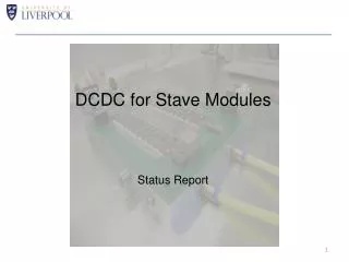
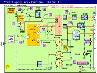
DCDC for 250nm Stave and ABC130 Hybrid - Revisited. Current DCDC Stavelet with DCDC tape added. Detail. Converter and module power connections. V+. V+. Gnd. Gnd. Gnd. Vin. One-wire control. Proposed Topology with Star Point. Star Point Power Feed to Converters

E N D
DCDC for 250nm Stave and ABC130 Hybrid - Revisited
Current DCDC Stavelet with DCDC tape added Detail Converter and module power connections V+ V+ Gnd Gnd Gnd Vin One-wire control
Proposed Topology with Star Point Star Point Power Feed to Converters (equidistant to power entry to hybrids and converters) 27.75 27.75 FILTER FILTER COIL/REG COIL/REG 7.5 Converter mirrored Converter retains original topology and orientation Ideal “Balanced” topology (as a single board?) Input O/P REG FILTER REG FILTER O/P COIL COIL All dimensions in mm
ABC130 Left & Right Handed Hybrid - Modules Original proposal – same flavour hybrids Hybrid-module topology is asymmetrical Revised proposal – Left & Right handed hybrids Hybrid-module topology is symmetrical 15mm 15mm 33.75mm 48.75mm 48.75mm 63.75mm Sensor outline shown in blue
ABC130 Left & Right Handed Hybrid - Detail • Capacitor arrays used throughout for power supply decoupling and AC-coupling of stave-side signalling • Supply decoupling 0508 100nF,10V • Stave-side signalling 0508 & 0504 • 220pF, 50V Left-Handed Hybrid “New” Right-Handed Hybrid • HCC Bond pad detail revisited to accommodate different flavoured hybrids • Results in a very linear layout in both instances • Would still like HCC hybrid side bond pad I/O to be configurable i.e. Match the pads to differing hybrid topologies • ABC130 common bus routing for the right-handed hybrid not so easy – but possible
ABC130 Common Bus Routing • ABC130s rotated 180° on right-handed hybrid • Bus connection is ‘locked’ to one side of ABC130 • “Final” ABC130 is now adjacent to HCC • Preferred direction of signal flow shown in blue • Ease of routing with linear layout • Minimises stub length connection to asics • Results in ‘long’ trace length (~200mm) • Increased capacitive load to HCC drivers • ~40pF from trace alone (cf ~2pF/cm) • Left-Handed hybrid has half the load • Issue for HCC (fast data clock)? • Or • Route as an asymmetric T (shown red) • End termination now moved to opposite end • Consider • Have receivers available on both sides of ABC130 • Bus topology becomes as left-handed hybrid • Need to understand more the implications of locking the • ABC130 bus connection to one side of the device • How does this impact the Endcap/Petals? End Termination embedded within final ABC130 ABC130 Bus ABC130 Bus End Termination embedded within final ABC130 End Termination for T bus Right-Handed Hybrid Left-Handed Hybrid