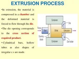
EXTRUSION PROCESS
EXTRUSION PROCESS. PRESENTED BY. ALOK KUMAR. EXTRUSION Continuous Process

EXTRUSION PROCESS
E N D
Presentation Transcript
EXTRUSION PROCESS PRESENTED BY ALOK KUMAR
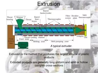
EXTRUSION Continuous Process In principle, the plastic raw material is plasticated by means of a screw plastication unit and the molten material is continuously pumped out through a standard orifice (die) in order to take the shape and then the shape is set by cooling/sizing system. Example:Film,Pipe,Tube, Profile, Monofilament, Box Strapping etc.
Single Screw Extruder Parts & its functions Screw Pump : Combination of Screw & Barrel Hopper : Funnel like device, mounted on Hopper throat. Holds a constant reserve of material. Barrel : Cylindrical housing in which the screw rotates. Hopper Throat : Circular opening at the feed end through which the material enters the screw pump. Drive System : AC/DC drives Speed reduction gear box Transmission system
Screw Support Assembly Typical thrust bearing assembly – Single Screw Extruder
Definition of terms • Compression Ratio - Is the ratio between the channel depth is the feed zone to that of the metering zone. • - Usually from 1.5 to 4:1 • L/D ratio - Length to nominal dia of screw • - usually 20 to 22:1 • Important Specification • Nominal dia of screw • Output(kgs/hr)
Zones of Extruder & its Functions: Feed Zone - Transport the material from hopper to compression zone. - Compacts, eliminates air gap Compression Zone - Transport the material from compression to metering zone. - Softens the material Metering zone - Melts, Mixes, the material pressurizes and pumps the melt.
Breaker Plate & Screen Pack • Breaker plate: Perforated circular metallic disc of about 4-5 mm thick. • Functions - Support for Screen pack - Converts the Spiral flow of melt in to stream lined laminar flow - Holds back contamination and unmelted particles. • Screen Pack • - Wire mesh 40,60,80 • - Arrests the unmelted particles and contamination • - Helps in developing back pressure
Extruder Screws • General purpose screw • PVC screw • Nylon screw • Two stage screw/vented screw • Segmented screws is also available for special purpose General purpose screw PVC screw
Nylon screw Two stage screw/vented screw
Mixing elements • Incorporated in the metering zone of screw • Several designs • Mainly to improve mixing, homogeneity PIN TYPE DULMAGE TYPE CAVITY TRANSFER TYPE
SCREW COOLING • Helps in Extracting out the Frictional Heat • Also helps in developing back pressure
Barrel • High grade steel cylinders • Has to withstand up to 400 atm. • Iron Based AlloyComplex non-ferrous alloys • More hard & less corrosion less hard & more corrosion • resistant resistant • These expensive materials are used as liners in steel barrels. • Barrels of Nitrided steel are also used. • They are Cheap, hard, less resistant to corrosion. • Screw material • Low carbon alloy steel • Flight tips are hardened by flame hardening to prevent wear or nitriding the entire screw. • Chrome plated screws for vinyl polymers • special nickel alloy steel for processing of saran.
Melt Fracture • It is a die-entry effect • In any converging flow there are tensile and shear forces • If tensile stresses become large and if they exceed the tensile strength of melt, the desirable smooth laminar flow is lost completely. • The extrudate emerging from die exit will be of irregular shape. This phenomena is called “Melt fracture”. If die entrance is tapered • Dead spots are eliminated • Minimise development of tensile stresses and hence minimise distortion of stream lines.
Shark skin & Bambooing effect • Shark skin • Roughening of the surface of the extrudate • The melt as it proceeds along the die channel, has a velocity profile with maximum at the centre and zero at the wall. • As it leaves the die lips, the material at the wall has to accelerate to the velocity at which the extrudate is leaving the die. • This generates tensile stress and if the stress exceeds Tensile strength, the surface ruptures causing the visual defect - “shark skin”. • If the conditions causing shark skin becomes more intensive, eg. Pressure at the extruder becomes excessive or die temperature drops, the extrudate “snaps back” -- “Bambooing effect”.
Die Swell • Also known as Extrudate swell. • When the melt emerges out of the die lips, there will be expansion in the direction perpendicular to flow and contraction in the direction parallel to flow. • Constrained molecules tends to relax at the die outlet. This leads to die swell. • This is nullified by higher take off speed.
Factor Direction of change Output Screw speed Increase Increase Channel depth Increase Increase Helix angle Increase(max. upto 300) Increase Back Pressure Decrease Increase Length of Metering sectio Increase Increase Viscosity Increase Decrease Factors Influencing Extruder Output
Twin Screw Extruder • Two screws rotating inside a barrel. • Intermeshing type are more popular. • Different models/design available
Basic Types • Co-rotating • Counter-rotating • Mainly used for preparation of master batches/colour concentrates • Co-rotating Twin screw - used for compounding all thermoplastics except PVC. • Counter rotating - preferred for PVC.
Sl.No. Co-rotating Counter rotating 1 Both screws either turn clock-wise or counter clock-wise. One screw turns clockwise and other counter clockwise. 2 More complete self wiping Less self wiping 3 Less likelihood of material stagnation More likelihood of material stagnation 4 Better mixing Less than co-rating 5 Total shear is more Less shear compared to co-rotating and single screw extruder 6 Mostly for compounding of TP Mainly for PVC compounding 7 Positive pumping Positive pumping 8 Less power consumption than single screw Less power consumption than Single screw. Comparison between Co-rotating and Counter rotating
APPLICATIONS OF EXTRUSION 1. Film: Blown film, Cast film, Co-extruded films, BOF. Material Used: PP,PVC, LDPE, HDPE, PET, Nylon etc. 2. Pipe/tube Material: HDPE, LDPE, LLDPE, PVC etc. 3. Sheet Material: HDPE, ABS, HIPS, PC etc. 4. Monofilament Material: PP, Nylon etc. 5. Extrusion Coating/Lamination Coated Playing Cards, Wrapping and LDPE laminated Woven sacks Material: LD,PP,HDPE 6. Box Strapping Material: PP, HDPE etc. 7. Tape/Woven Sack Material: PP, HDPE 8. Wire Coating/Covering Primary/Secondary insulation Material: LDPE, PVC (Primary insulation) Nylon (secondary insulation) 9. Profiles ( Door and window ) Material: PVC
Blown film extrusion • Upward blown film - LD,HD,PVC, Nylon etc. • Downward blown film - PP (Mainly to get clarity) • Process outline • Melt emerging from extruder is inflated by air pressure (3 to 4 kgs/cm2) • Bubble is properly stabilized and cooled • Wound on the winder
BLOWN FILM DIES SIDE FEED DIE CENTRE FEED DIE SPIRAL FLOW DIE
TQ process • Tabular quench film process • For PP
FLAT FILM - EXTRUSION • The Melt emerging out of the die lips strikes the chrome plated chill roll where it solidifies. • Subsequently the film is pulled through nip rolls . • Trimming blades trims-off the thicker edges. • Then the film is wound on the winder.
Blown Film Co-Extrusion • Barrier properties is the main reason to go for multi layer film Three layer Co-Extrusion Five layer Co-Extrusion
5- Layer Blown film Die with Radial melt distributor
SL.NO MATERIAL COMBINATION SPECIAL PROPERTIES MOST IMPORTANT FIELDS OF APPLICATION 1. LDPE/LDPE Pinhole-free ( multicolored) Milk film and carrier bags 2. LDPE/EVA Good weldability, sterilizable Heavy duty bags, medical articles 3. HDPE/LDPE Good strength Bakery goods food stuffs, tomato concentrate 4. LLDPE/EVA Good surface adhesion Stretch film 5. Ionomers/PA Gas and aroma-tight Meat, sausage, fish and cheese 6. Ionomers/EVA Grease proof Coconut, biscuit 7. LDPE/HDPE/LDPE Weldability on both sides reduced curling tendency like 3 8. LDPE/TL/PA Gas water and aroma tight Readymade meals, sausage, fish, cheese foamed PS granulate 9. LDPE/TL/PA/TL/LDPE or LLDPE/TL/PA/TL/LLDP No curling tendency improved barrier properties, as PA protected against moisture absorption improved layer adhesion weldalble on both sides Like 8
Extrusion coating • The plastic is coated over a substrate like paper, by extruding through a slot die downward between two rolls. • Substrate is fed between the molten plastic and the roll and is joined with the plastic by pressure between rolls without the use of an adhesive. • Material used LDPE & PVC • PP, HDPE, Ionomer etc. are also used. • Equipment compresses of • Pre treatment unit • Coating unit • Take off & winding
Dies • Coat hanger die • ‘T’ type die
Tube/Pipe Extrusion • Wall thickness & flexibility/Rigidity differentiates between tube/pipe • Pipes are produced by horizontally extruding molten polymer through an annuler opening into several sizing, cooling devices that stabilizes the final dimension. • Comprises of • Extruder • Die • Sizing device • Cooling bath • Cater puller • Cutter or winder
Dies used • Straight through • Off set die
Sizing Equipment - Methods • Vacuum Trough • Widely used • With the help of vacuum, Pipe is stabilized and sized to retain the shape • Sizing Sleeve • Methods fixes the outside pipe diameter as it hardens by contact with a water cooled metal sleeve. FLOATING PLUG SYSTEMS- USED FOR RIGID PIPES OF MEDIUM AND LARGE SIZES TO PREVENT LOSS OF AIR PRESSURE FLOATING PLUG SYSTEM IS USED
Extended Mandrel • Method uses a water cooled extended mandrel • Provides additional internal cooling and internal support • Sizing plate • Method involves pulling the pipe through a series of brass plates • Mainly for small dia pipes/tubes.
Sheet Extrusion • Process out line • Plasticated melt in pumped out through the sheeting die by screw pump • Molten sheet emerging from die lips is feed through three roll calendar, cooling rolls and subsequently pulled by Nip rolls. • Cut the sheet by shear cutter • Stacking/ Inspection
Dies T-TYPE DIE COAT HANGER TYPE DIE ( Widely Used) Coat Hanger type of Die is much more stream lined than T-type Die
Wire Coating/Cable Covering • Unit comprises of • Un wind unit (For conductor) • Pre treatment unit • Wire coating unit • Steps Involved • Wire/conductor is unwound & straightened by Tension • Control Unit. • Pre treated to promote adhesion of molten plastic • Then passed through the Cross head die of the coating unit • Coated wire is then cooled by passing through cooling trough • Wound on the winder • Cooling Trough • Take off/ wind up.
Die used • Tubing die USED MAINLY FOR SECONDARY INSULATION • Pressure die USED MAINLY FOR PRIMARY INSULATION
Extrusion of Mono filaments • Mono filaments are wise like polymer strands of dia 0.09 to 1.52 mm. • Usually they have circular cross-section. • The polymer melt from extruder is pumped out through a multi-hole die, quenched, stretched/oriented and annealed to get the filament of enhanced properties. • The production process comprises of • Extrusion • Filament forming • Stretching (orientation) • Annealing • Winding
Orientation Systems Heated liquid bath method Heated oven method Heated point method Heated roll method Depending upon material & configuration system is selected C A B D
Extrusion -- Box- Strappings • The process sketch is similar to Monofilament line except the die – A slotted die is used in place of multi-hole monofilament die • Plastic Strappings, made of PP/HDPE replace iron because of their flexibility. • Process outline • Plasticated melt from an extruder is pumped out through a slot die • Quenched in water bath • Bath temperature - 800C for PP • - 900C for PA-6 • Passed through a orientation system and stretched to about 8 times in order to improve tensile properties. • Annealed in an annealing chamber to relieve the stresses • Wound on winder.
Special Extrusion Process • Corrugated Pipes • Similar to extrusion of pipes except the die and the calibration units are specially designed to produce corrugation on the pipe. • The cylindrical part of the pipe die head extends in to the closed area of a revolving mould block chain. • The plastic tube is pressed against the profiled, revolving mould block halves by internal air pressure or by vacuum calibration. • As it passes through the forming machine its cools and solidifies. a) Internal Pressure System b) Vacuum System
POST EXTRUSION FORMING Inline post forming with extruder embossing one or both sides with shallow or deep patterns
INLINE VACUUM/PRESSURE FORMER FOR PLASTIC SHEEET WITH MATCHED, WATER COOLED FORMING MOULDS ON CONTINOUS CONVEYOR SYSTEM AN INLINE COIL FORMER CAN PRODUCE TELEPHONE CORDS
THANK ‘U’