Download
1 / 11
110 likes | 278 Views
Circuit with zero initial conditions. Input is 1u(t) V or 1u(t) A. Output (a voltage or a current) is the “unit step response”. Lecture #18 EGR 260 – Circuit Analysis. Reading Assignment: Chapter 7 in Electric Circuits, 9 th Ed. by Nilsson . Unit step response to a circuit

E N D
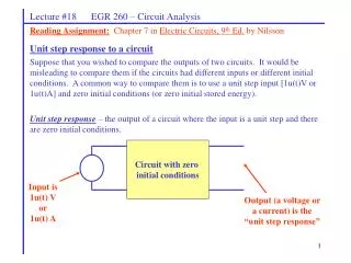
Circuit with zero initial conditions Input is 1u(t) V or 1u(t) A Output (a voltage or a current) is the “unit step response” Lecture #18 EGR 260 – Circuit Analysis Reading Assignment:Chapter 7 in Electric Circuits, 9th Ed. by Nilsson Unit step response to a circuit Suppose that you wished to compare the outputs of two circuits. It would be misleading to compare them if the circuits had different inputs or different initial conditions. A common way to compare them is to use a unit step input [1u(t)V or 1u(t)A] and zero initial conditions (or zero initial stored energy). Unit step response – the output of a circuit where the input is a unit step and there are zero initial conditions.
Lecture #18 EGR 260 – Circuit Analysis Example:Find the unit step response for VC(t) in the circuit shown below.
Lecture #18 EGR 260 – Circuit Analysis Reading Assignment:Chapter 8 in Electric Circuits, 7th Ed. by Nilsson Chapter 8 – Second-Order Circuits Order of a circuit Order of the differential equation (DE) required to describe the circuit The number of independent* energy storage elements (C’s and L’s) = = * C’s and L’s are independent if they cannot be combined with other C’s and L’s (in series or parallel, for example) Example: Draw several circuits with C’s and L’s and identify the order of each circuit.
Lecture #18 EGR 260 – Circuit Analysis • 2nd-order circuits have 2 independent energy storage elements (inductors and/or capacitors) • Analysis of a 2nd-order circuit yields a 2nd-order differential equation (DE) • A 2nd-order differential equation has the form: • Solution of a 2nd-order differential equation requires two initial conditions: x(0) and x’(0) • All higher order circuits (3rd, 4th, etc) have the same types of responses as seen in 1st-order and 2nd-order circuits • Since 2nd-order circuits have two energy-storage types, the circuits can have the following forms: • 1) Two capacitors • 2) Two inductors • 3) One capacitor and one inductor • A) Series RLC circuit * • B) Parallel RLC circuit * • C) Others • * The textbook focuses on these two types of 2nd-order circuits
Lecture #18 EGR 260 – Circuit Analysis Form of the solution to differential equations As seen with 1st-order circuits in Chapter 7, the general solution to a differential equation has two parts: x(t) = xh + xp = homogeneous solution + particular solution or x(t) = xn + xf = natural solution + forced solution where xh or xn is due to the initial conditions in the circuit and xp or xf is due to the forcing functions (independent voltage and current sources for t > 0). The forced response The forced response is due to the independent sources in the circuit for t > 0. Since the natural response will die out once the circuit reaches steady-state, the forced response can be found by analyzing the circuit at t = . In particular, xf = x()
Lecture #18 EGR 260 – Circuit Analysis The natural response A 2nd-order differential equation has the form: where x(t) is a voltage v(t) or a current i(t). To find the natural response, set the forcing function f(t) (the right-hand side of the DE) to zero. Substituting the general form of the solution Aest yields the characteristic equation: s2 + a1s + ao = 0 Finding the roots of this quadratic (called the characteristic roots or natural frequencies) yields: The roots of the quadratic equation above may be real and distinct, repeated, or complex. Thus, the natural response to a 2nd-order circuit has 3 possible forms:
Lecture #18 EGR 260 – Circuit Analysis • 1) Overdamped response • Roots are real and distinct [ (a1)2 > 4ao ] • Solution has the form: • Sketch the form of the solution. • Discuss the concept of the dominant root.
Lecture #18 EGR 260 – Circuit Analysis • 2) Critically damped response • Roots are repeated [ (a1)2 = 4ao ] so s1 = s2 = s = -a1/2 • Solution has the form: • Sketch the form of the solution.
Lecture #18 EGR 260 – Circuit Analysis 3) Underdamped response Roots are complex [ (a1)2 < 4ao ] so s1 , s2 = j Show that the solution has the form: Sketch the form of the solution. Discuss the concept of the exponential envelope. Sketch xn if A1 = 0, A2 = 10, =-1, and = . Sketch xn if A1 = 0, A2 = 10, =-10, and = 100.
Lecture #18 EGR 260 – Circuit Analysis Illustration: The transient response to a 2nd-order circuit must follow one of the forms indicated above (overdamped, critically damped, or underdamped). Consider the circuit shown below. v(t) is 0V for t < 0 and the steady-state value of v(t) is 10V. How does it get from 0 to 10V? Discuss the possible responses for v(t) Define the terms damping, rise time, ringing, and % overshoot
Lecture #18 EGR 260 – Circuit Analysis • Examples: When is each of the 3 types of responses desired? Discuss the following cases: • An elevator • A cruise-control circuit • The output of a logic gate • The start up voltage waveform for a DC power supply


