Download
1 / 29
310 likes | 488 Views
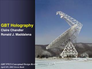
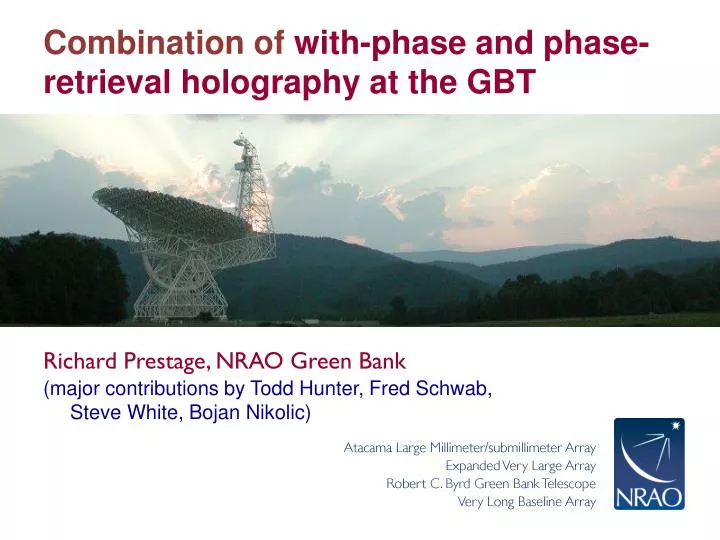
Combination of with-phase and phase-retrieval holography at the GBT. Richard Prestage, NRAO Green Bank. (major contributions by Todd Hunter, Fred Schwab, Steve White, Bojan Nikolic ). 485 ft. At 100 m, the GBT is the largest fully steerable telescope in the world.

E N D
Combination of with-phase and phase-retrieval holography at the GBT • Richard Prestage, NRAO Green Bank • (major contributions by Todd Hunter, Fred Schwab, Steve White, BojanNikolic)
485 ft At 100 m, the GBT is the largest fully steerable telescopein the world. 2.3 acre collecting area 305 ft
Characteristics of the GBT Large Collecting Area Sensitive to Low Surface Brightness Sky Coverage & Tracking (>85%) Angular Resolution Frequency Coverage Radio Quiet Zone Unblocked Aperture state-of-art receivers & detectors modern control software flexible scheduling The Advantage of Unblocked Optics Dynamic Range Near sidelobes reduced by a factor >10 from conventional antennas Gain & Sensitivity The 100 meter diameter GBT performs better than a 120 meter conventional antenna Reduced Interference
GBT Active Surface 2004 panels, 1.57mm 6061 T6 aluminum skins epoxied to rib frame, CMM-measured rms < 75 μm (mean=60) 2209 actuators (located at panel corner intersections)
Actuator specifications • Stroke = 51 mm (≈ 4x the requirement) • Speed = 250 microns /second • Static load (axial and side) = 481 kg • Lifetime = 20 years (at 60 meter /year) • Motor type = DC brush • Position sensor = LVDT • Resolution ~ 25 microns • Repeatability < 50 microns • Temperature effect ~16 microns rms • Control system • 139 pairs of modules • Each with up to 16 actuators
Concerns with LRF Performance • How to measure Group Index of Refraction • Geometry of system: “long skinny triangles”; relaying coordinate systems • System Integration Concerns • Difficulty of integrating LRF usage into GBT control software, and astronomical (incremental, differential) improvements to pointing and surface adjustments
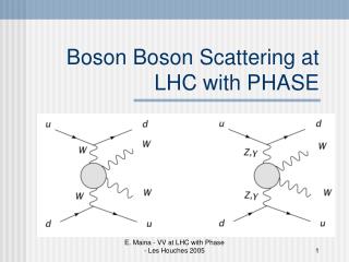
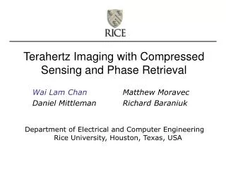
High-resolution interferometric holography • Technique is > 30 years old (Bennett et al. 1976) • Measure complex beam pattern (phase and amplitude) • Fourier transform to get phase and amplitude of E field on aperture • Convert phase to surface error, and apply mechanical corrections • 2 Receivers: room-temp. LNBs, 10kHz filters, Hilbert transform correlator • Reference receiver at top offeed arm • Main receiver inGregorian turret
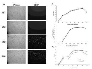
Satellite target Galaxy 28 • 2°x2° map, 200 rows 3.5 hours 50 MHz Galaxy 28 = geostationary TV broadcaster Elevation = 44°, well-behaved orbit 11.702 GHz CW beacon (stable to < kHz) Effective flux density ~ 106 Jy in 10 kHz filter Typical system phase stability (receiver + atmosphere) = 2° in 36 msec integrations Corresponds to 70 microns surface rms
High-resolution interferometric holography • Actuator “influence function” revealed 2000
Identification of “twin arc” pattern Observed beam Predicted beam gravity error -2°C thermal
Shape of individual panels (gravitational and thermal sag) is the dominant pattern FEM model Observed surface
S. von Hoerner (January 1971) Measured panel temperature gradients Panel deflection (mils) T (skin) – T (rib) T (skin) – T (air)
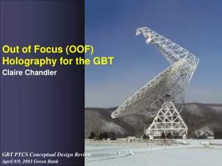
“Out-of-focus” (OOF) Holography Any telescope surface pattern can be conveniently expressed as a sum of Zernike patterns. GBT active surface can apply up through n=7 (36 terms). n=1 But not quite orthonormal (due to the receiver illumination taper) n=2 n=3
Out-of-Focus (OOF) Holography Technique Model is fit to the time stream data. Result is the aperture phase image that can be applied to correct the surface: 2. Fit with a small number of (5-7) Zernike polynomials Model 1. Acquire raster maps of a quasar at 3 focus settings
Thermal distortions due to solar heating Surface returns to nighttime performance before the ambient temperature drops Time
“AutoOOF” tool integrated into the GBT user interface (ASTRID)
Estimated surface error budget (2010) • Small-scale errors • Panel manufacturing error plus gravity 127 microns (known) • Panel-scale thermal error (nighttime sag) 100 microns (model) • Subreflector surface rms (photogrammetry) 100 microns (known) • Panel setting (actuator + panel corners) 80 microns (estimated) • Actuator repeatability 50 microns (known) • Intermediate-scale gravity and thermal errors 80 microns (estimated) • Residual large-scale thermal error 80 microns (known) • Total root-sum-squared surface error 240 microns
Results URSI, Boulder, CO Jan. 7, 2009
FutureDevelopments • “Next Generation” metrology system • Fixed baseline system, range and angle measurements made by instruments mounted on GBT. • Relay a fiducial coordinate created at the pintle bearing by high performance inclinometers (like “ALMA reference telescope”) • Use a two-tone system with incommensurate frequencies • DDS synthesizers • MEMS fiber optic switches • Have a “brass-board” of this, functions well.
Predicted Results Metrologies at Radio Astronomy Antennas September 1 – 2, 2014
Alternatives? Image courtesy of NRAO/AUI