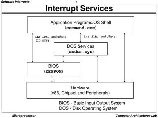

8085 Interrupts and Handling Techniques
E N D
Presentation Transcript
Introduction • Interrupt is a process where an external device can get the attention of the microprocessor. • The process starts from the I/O device • The process is asynchronous. • Interrupts can be classified into two types: • Maskable(can be delayed) • Non-Maskable(can not be delayed) • Interrupts can also be classified into: • Vectored(the address of the service routine is hard-wired) • Non-vectored(the address of the service routine needs to be supplied externally)
Introduction • An interrupt is considered to be an emergency signal. • The Microprocessor should respond to it as soon as possible. • When the Microprocessor receives an interrupt signal, it suspends the currently executing program and jumps to an Interrupt Service Routine(ISR) to respond to the incoming Interrupt. • Each interrupt will most probably have its own ISR.
Responding to interrupt • Responding to an interrupt may be immediate or delayed depending on whether the interrupt is maskable or non-maskable and whether interrupts are being masked or not. • There are two ways of redirecting the execution to the ISR depending on whether the interrupt is vectored or non-vectored. • The vector is already known to the Microprocessor • The device will have to supply the vector to Microprocessor
8085 Interrupt • The maskable interrupt process in the 8085 is controlled by a single flip flop inside the microprocessor. • This Interrupt Enable flip flop is controlled using the two instructions “EI” and “DI”. • The 8085 has a single Non-Maskable interrupt. • The non-maskable interrupt is not affected by the value of the Interrupt Enable flip flop.
8085 Interrupt • The 8085 has 5 interrupt inputs. • The INTR input. • The INTR input is the only non-vectored interrupt. • INTR is maskable using the EI/DI instruction pair. • RST 5.5, RST 6.5, RST 7.5 are all automatically vectored. • RST 5.5, RST 6.5, and RST 7.5 are all maskable. • TRAP is the only non-maskableinterrupt in the 8085 • TRAP is also automatically vectored
Interrupt Vector • An interrupt vector is a pointer to where the ISR is stored in memory. • All interrupts (vectored or otherwise) are mapped onto a memory area called the Interrupt Vector Table(IVT). • The IVT is usually located in memory page 00(0000H -00FFH). • The purpose of the IVT is to hold the vectors that redirect the microprocessor to the right place when an interrupt arrives. • The IVT is divided into several blocks. Each block is used by one of the interrupts to hold its “vector”
Non-Vectored Interrupt • The interrupt process should be enabled using the EI instruction. • The 8085 checks for an interrupt during the execution of every instruction. • If there is an interrupt, the microprocessor will complete the executing instruction, and start a RESTART sequence. • The RESTART sequence resets the interrupt flip flopand activates the interrupt acknowledge signal (INTA). • Upon receiving the INTA signal, the interrupting device is expected to return the op-code of one of the 8 RST instructions.
Non-Vectored Interrupt • When the microprocessor executes the RST instruction received from the device, it saves the address of the next instruction on the stack and jumps to the appropriate entry in the IVT. • The IVT entry must redirect the microprocessor to the actual service routine. • The service routine must include the instruction EI to re-enable the interrupt process. • At the end of the service routine, the RET instruction returns the execution to where the program was interrupted.
Restart Sequence • The restart sequence is made up of three machine cycles • In the 1st machine cycle: • The microprocessor sends the INTA signal. • While INTA is active the microprocessor reads the data lines expecting to receive, from the interrupting device, the opcode for the specific RST instruction. • In the 2nd and 3rd machine cycles: • the 16-bit address of the next instruction is saved on the stack. • Then the microprocessor jumps to the address associated with the specified RST instruction.
Masking • These three interrupts are masked at two levels: • Through the Interrupt Enable flip flop and the EI/DI instructions. • The Interrupt Enable flip flop controls the whole maskable interrupt process. • Through individual mask flip flops that control the availability of the individual interrupts. • These flip flops control the interrupts individually.
Manipulating the Mask • The Interrupt Enable flip flop is manipulated using the EI/DI instructions. • The individual masksfor RST 5.5, RST 6.5 and RST 7.5 are manipulated using the SIM instruction. • This instruction takes the bit pattern in the Accumulator and applies it to the interrupt mask enabling and disabling the specific interrupts.
SIM and Interrupt Mask • Bit 0 is the mask for RST 5.5, bit 1 is the mask for RST 6.5 and bit 2 is the mask for RST 7.5. • If the mask bit is 0, the interrupt is available. • If the mask bit is 1, the interrupt is masked. • Bit 3 (Mask Set Enable -MSE) is an enable for setting the mask. • If it is set to 0 the mask is ignoredand the old settings remain. • If it is set to 1, the new setting are applied. • The SIM instruction is used for multiple purposes and not only for setting interrupt masks. • It is also used to control functionality such as Serial Data Transmission. • Therefore, bit 3 is necessary to tell the microprocessor whether or not the interrupt masks should be modified
Triggering Level • RST 7.5 is positive edge sensitive. • When a positive edge appears on the RST7.5 line, a logic 1 is stored in the flip-flop as a “pending” interrupt. • Since the value has been stored in the flip flop, the line does not have to be high when the microprocessor checks for the interrupt to be recognized. • The line must go to zero and back to onebefore a new interrupt is recognized. • RST 6.5 and RST 5.5 are level sensitive. • The interrupting signal must remain present until the microprocessor checks for interrupts.
RIM instruction • Bits 0-2 show the current setting of the mask for each of RST 7.5, RST 6.5 and RST 5.5 • They return the contents of the three mask flip flops. • They can be used by a program to read the mask settings in order to modify only the right mask. • Bit 3 shows whether the maskable interrupt process is enabled or not. • It returns the contents of the Interrupt Enable Flip Flop. • It can be used by a program to determine whether or not interrupts are enabled.
RIM instruction • Bits 4-6 show whether or not there are pending interrupts on RST 7.5, RST 6.5, and RST 5.5 • Bits 4 and 5 return the current value of the RST5.5 and RST6.5 pins. • Bit 6 returns the current value of the RST7.5 memory flip flop. • Bit 7 is used for Serial Data Input. • The RIM instruction reads the value of the SID pin on the microprocessor and returns it in this bit.
Trap • TRAP is the only non-maskable interrupt. • It does not need to be enabled because it cannot be disabled. • It has the highest priority amongst interrupts. • It is edge and level sensitive. • It needs to be high and stay high to be recognized. Once it is recognized, it won’t be recognized again until it goes low, then high again. • TRAP is usually used for power failure and emergency shutoff.
Additional Concepts • Programmable Interrupt Controller 8259 A • A programmable interrupt managing device • It manages 8 interrupt requests. • It can vector an interrupt anywhere in memory without additional H/W. • It can support 8 levels of interrupt priorities. • The priority scheme can be extended to 64 levels using a hierarchy 0f 8259 device.
Features • Can manage 8 interrupts • Can be cascaded with another 8259 to increase the interrupts to 64. • Internal priority resolver. • Individually mask each interrupt request. • Read the status of pending , in-service and the masked interrupts