Download
1 / 29
300 likes | 553 Views
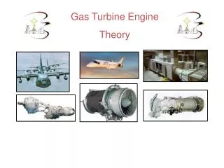
Gas Turbine Theory and Construction. Introduction. Comprehend the thermodynamic processes occurring in a gas turbine Comprehend the basic components of gas turbine engines and their basic operation Comprehend the support systems associated with gas turbine engines. Background.

E N D
Introduction • Comprehend the thermodynamic processes occurring in a gas turbine • Comprehend the basic components of gas turbine engines and their basic operation • Comprehend the support systems associated with gas turbine engines
Background • Aircraft turbojet/turbofan engines are precursors to gas turbines • Installed for propulsion in: • FFG’s • DD’s • DDG’s • CG’s • M-1 tanks • Also used for electrical generation & auxiliary applications
Advantages of GTE’s • Weight reduction of 70% • Simplicity • Reduced manning requirements • Quicker response time • Faster Acceleration/deceleration • Modular replacement • Less vibrations • More economical
Disadvantages of GTE’s • Many parts under high stress • High pitched noise • Needs large quantities of air • Large quantities of hot exhaust (target) • Cannot be repaired in place
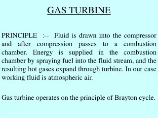
Brayton Cycle • Unlike diesels, operate on STEADY-FLOW cycle • Open cycle, unheated engine 1-2: Compression 2-3: Combustion 3-4: Expansion through Turbine and Exhaust Nozzle (4-1: Atmospheric Pressure)
Basic Components • Compressor • Draws in air & compresses it • Combustion Chamber • Fuel pumped in and ignited to burn with compressed air • Turbine • Hot gases converted to work • Can drive compressor & external load
Basic Components • Compressor • Draws in air & compresses it • Combustion Chamber • Fuel pumped in and ignited to burn with compressed air • Turbine • Hot gases converted to work • Can drive compressor & external load
Basic Components • Compressor • Draws in air & compresses it • Combustion Chamber • Fuel pumped in and ignited to burn with compressed air • Turbine • Hot gases converted to work • Can drive compressor & external load
Compressor • Supplies high pressure air for combustion process • Compressor types • Radial/centrifugal flow compressor • Axial flow compressor
Compressor • Radial/centrifugal flow • Adv: simple design, good for low compression ratios (5:1) • Disadv: Difficult to stage, less efficient • Axial flow • Good for high compression ratios (20:1) • Most commonly used
Compressor • Controlling Load on Compressor • To ensure maximum efficiency and allow for flexibility, compressor can be split into HP & LP sections • Vane control: inlet vanes/nozzle angles can be varied to control air flow • Compressor Stall • Interruption of air flow due to turbulence
Use of Compressed Air • Primary Air (30%) • Passes directly to combustor for combustion process • Secondary Air (65%) • Passes through holes in perforated inner shell & mixes with combustion gases • Film Cooling Air (5%) • Insulates/cools turbine blades
Combustion Chambers • Where air & fuel are mixed, ignited, and burned • Spark plugs used to ignite fuel • Types • Can: for small, centrifugal compressors • Annular: for larger, axial compressors (LM 2500) • Can-annular: for really large turbines
Turbines • Consists of one or more stages designed to develop rotational energy • Uses sets of nozzles & blades
Turbines • Split Shaft • Gas generator turbine drives compressor • Power turbine separate from gas generator turbine • Power turbine driven by exhaust from gas generator turbine • Power turbine drives power coupling
Single Shaft • Efficiently operates at constant speeds • Used in GTGS (gas turbine generator systems) • Single shaft • Power coupling on same shaft as turbine • Same shaft drives rotor of compressor and power components *Primarily used for electric power because of constant speed, regardless of load.
Split Shaft • Best where speeds and loads vary • Used in LM-2500 • Power shaft is decoupled from compressor • Allows both to operate at efficient speeds (not the same) *More suitable for main propulsion applications due to the fact that the gas generator turbine and power turbine operate near their most efficient speeds throughout a RANGE of load demands.
Accessory Drive Assembly • Purpose - Provides motive force for driving the accessories required for operation and control of engine • Attached Accessory Equipment • Fuel oil pump • Lube oil pump • Starter (pneumatic, electric, hydraulic)
Gas Turbine Systems • Air System • Air intakes are located high up & multiple filters • Exhaust discharged out stacks • Fuel System • Uses either DFM or JP-5 • Lubrication System • Supply bearings and gears with oil
Gas Turbine Systems • Starting System • To get compressor initially rotated, HP air used (can use electrical also) • Once at certain RPM, fuel injected and spark ignited • Power Transmission System • Reduction gears used to transfer torque • With split shaft, turbines can run @ different speeds