SOLUTION USING THEVENIN’S THEOREM
SOLUTION USING THEVENIN’S THEOREM.

SOLUTION USING THEVENIN’S THEOREM
E N D
Presentation Transcript
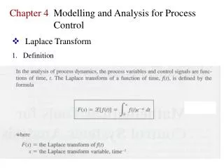
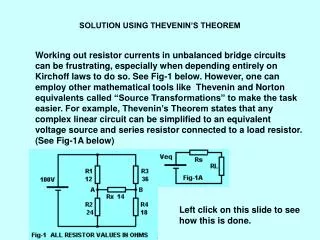
SOLUTION USING THEVENIN’S THEOREM Working out resistor currents in unbalanced bridge circuits can be frustrating, especially when depending entirely on Kirchoff laws to do so. See Fig-1 below. However, one can employ other mathematical tools like Thevenin and Norton equivalents called “Source Transformations” to make the task easier. For example, Thevenin’s Theorem states that any complex linear circuit can be simplified to an equivalent voltage source and series resistor connected to a load resistor. (See Fig-1A below) Left click on this slide to see how this is done.
Procedure: • Call Rx the Load Resistor (See Fig-1 below) • Remove Rx and calculate the Voltage potential between A & B This is the equivalent Voltage source. (See Fig-2 below) • Place a short across 100V and calculate resistance between A & B This result is the equivalent series resistance. (See fig-3 below) • Draw the series equivalent circuit and calculate the Rx current (See Fig.4 below) This result, 0.98A, is the current through Rx. Since the current through Rx (0.98A) is now known, the remaining currents in Fig-1 can be easily calculated using Kirchoff Laws.
KIRCHOFF LAWS • Kirchoff’s Current Law: The sum of all currents entering a node must be equal currents leaving the node. • Kirchoff Voltage Law: The sum of the voltages around a closed loop must equal to zero. • To set up the problem draw the circuit and make notations as follows: • Draw the circuit and enter Volts and resistance values (see Fig-5) • Using conventional current flow (+ to -) enter arrows indicating direction of current flow in all resistors Label unknown currents I1, I2, & I3 through R1, R2, & R3 respectively • Label R4 current as (I1 - I3 ) & R5 current as (I2 + I3)
KIRCHOFF LAWS • Since there are 3 unknowns currents (I1, I2 & I3), select 3 loops in Fig-5 and from these, develop 3 equations to be used for working out I1, I2 & I3. Loop 1:100V, R1 & R4 Loop 2: 100V, R2 & R5 Loop 3: R1, R2 & R3 Eq. 1: 100 – R1 I1 – R4(I1 – I3) = 0 Eq. 2: 100 – R2 I2 – R5(I2 + I3) = 0 Eq. 3: R1 I1 + R3 I3 –R2 I2 = 0 Substitute resistor values for R1, R2 & R3 Eq. 1A: 100 – 12 I1 – 24(I1 – I3) = 0 Eq. 2A: 100 – 36 I2 – 18(I2 + I3) = 0 Eq. 3A: 12 I1 + 14 I3 –36 I2 = 0
KIRCHOFF LAWS From previous slide Eq. 1A: 100 – 12 I1 – 24(I1 – I3) = 0 Eq. 2A: 100 – 36 I2 – 18(I2 + I3) = 0 Eq. 3A: 12 I1 + 14 I3 –36 I2 = 0 Expand to get rid of parentheses Eq. 1B: 100 – 12 I1 – 24I1 + 24I3 = 0 Eq. 2B: 100 – 36 I2 – 18I2 – 18I3 = 0 Eq. 3B: 12 I1 + 14 I3 –36 I2 = 0 Consolidating we get: Eq. 1C: 100 – 36 I1 + 24 I3 = 0 Eq. 2C: 100 – 54 I2 – 18 I3 = 0 Eq. 3C: 12 I1 + 14 I3 –36 I2 = 0 We have 3 simultaneous equations with 3 unknowns to find I1, I2 & I3. Now the fun begins.
From previous slide Eq. 1C: 100 – 36 I1 + 24 I3 = 0 Eq. 2C: 100 – 54 I2 – 18 I3 = 0 Eq. 3C: 12 I1 + 14 I3 –36 I2 = 0 These 3 equations can be reduced to two equations with two unknown currents using traditional algebra. The procedure is as follows: Multiply Eq. 1C through by 18: 18(100 – 36 I1 + 24 I3 = 0) to get: Eq. 1D: 1800 – 648 I1 + 432 I3 =0 Multiply Eq. 2C through by 24: 24(100 – 54 I2 – 18 I3 = 0) to get 2D: 2400 – 1296 I2 – 432 I3 =0 By Adding Eq. 1D to Eq. 2D we get: 4200 – 648 I1 – 1296 I2 or Eq. 4A: 4200 = 648 I1 + 1296 I2 (One of 2 equations with 2 unknowns) Repeat procedure using eq. 2C & 3C to get the other equation with 2 unknowns
KIRCHOFF LAWS Eq. 2C: 100 – 54 I2 – 18 I3 = 0 Eq. 3C: 12 I1 + 14 I3 –36 I2 = 0 Multiply Eq. 2C by 14 to get 14 (100 – 54 I2 – 18 I3 = 0) or: Eq. 2E: 1400 – 756 I2 – 252 I3 = 0 Multiply Eq. 3C by 18 to get 18(12 I1 + 14 I3 –36 I2 = 0) or: Eq. 3E: 216 I1 + 252 I3 – 648 I2 = 0 Add Eq. 3E to Eq. 2E to get 1400 + 216 I1 – 1404 I2 or Eq. 4B: 1400 = – 216 I1 + 1404 I2 (The 2nd Equation with 2 unknowns So now we have: Eq. 4A: 4200 = 648 I1 + 1296 I2 Eq. 4B: 1400 = – 216 I1 + 1404 I2 Multiply Eq. 4A by 1404 to get: Eq. 5A 5896800= – 909792 I 1 + 1819584 I2 Multiply Eq. 4B by 1296 to get: Eq: 5B 1814400 = 279936 I1 + 1819584 I2 Subtract Eq.5A from Eq. 5B to get: 4082400 = 1189728 I1 or I1= 3.43A
KIRCHOFF LAWS We calculated I1 = 3.43Agoing through R1. I3 Should be easy to find. Using the 100V, R1 R4 loop we get: 100 = (12 x 3.43) + 24(3.43 - I3) or 100 = 41.16 + 82.32 –24 I3 or 24 I3 = 23.48 I3 = 23.48 / 24 = 0.97833A ~ 0.98A As you can see from the above application of Kirchoff Laws, it takes a good working knowledge of Algebra and a close watch on the details. Even with these qualities, there are many pitfalls on the way to a solution: getting the signs wrong, arithmetic errors, misplacement of variables etc. I don’t think I want to ever repeat such an exercise again. When ever possible, choose the Thev enin Voltage equivalents or the Norton Current equivalents.