Download
1 / 24
240 likes | 431 Views
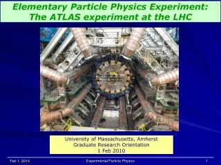
Commissioning with cosmic rays of the Muon Spectrometer of the ATLAS Experiment at LHC. Luca Spogli Università Roma Tre & INFN Roma Tre. LNF Frascati Spring School 2007. Outline. The ATLAS experiment at LHC Muon Spectrometer Commisioning Status Test with cosmic rays Summary .

E N D
Commissioning with cosmic rays of the Muon Spectrometer of the ATLAS Experiment at LHC Luca Spogli Università Roma Tre & INFN Roma Tre LNF Frascati Spring School 2007
Outline • The ATLAS experiment at LHC • Muon Spectrometer • Commisioning Status • Test with cosmic rays • Summary
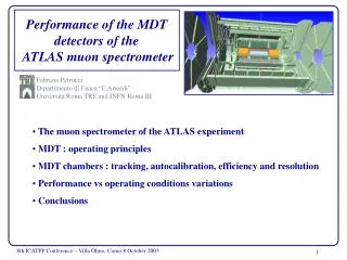
ATLAS detector Electromagnetic Calorimeter Muon Spectrometer Forward Calorimeter Solenoid Endcap Toroid Inner Detector Barrel Toroid Hadronic Calorimeter Radiation Shielding
MDT h=1 h=1.4 RPC TGC ECT CSC ~1200 chambers / ~7000 m2 Tubes per layer Layer per multilayer Chamber lenght (mm) Chamber heigth (mm) MDT (Monitored Drift Tubes) • good space resolution (~100 μm per point) • pt/pt 2-3% @ pt<200GeV/c • pt/pt 10% @ pt 1TeV/c
Time measurement rt-relation with a typical accuracy of 10µm MDT Calibration: r(t) • Drift time measurement • Determination of space-time relationship r(t) via autocalibration
Muon Reconstruction In a single multilayer Track segments MDT mutilayer Momentum measurement from sagitta determination p=0.3 Br
Installation and commissioning • Installation in the pit started in Summer 2005 • First tests with cosmic muons during Summer 2006 • First curved muon (magnetic field on) in November 2006 • MDT chamber installation completed in the barrel region
Installation • It is not an easy task...
Cosmics • 19-20 November data • Sector 13 with RPC timing informations • Magnetic field on-off • ~1 Mevents • 9 chambers • Many tests on MDT’s • Drift behavior • Calibration • Efficiency • Noise • Dead channels • Preliminary alignment • Some results in this talk Sector 13 Side A
Event Display BIL chamber
Fired tubes per event ...after noise reduction cuts Accidental trigger coincidences 4 multilayers 6 multilayers 2 multilayers Number of Fired Tubes / event
Impact of magnetic field on r(t) • B field parallel to the wire • Electrons do not travel straight forward radially • They travel under an angle ψ • Drift time t for a certain radius r increases B field expected to change drift-to-radius relationship by Lorentz angle τ: mean time between collisions
Z coordinate Measured muon spectra µ- µ+ Momentum (GeV) Ratio of µ+ / µ- = 1.48±0.27 Small shaft Big shaft • According to P.D.G • Charge ratio of cosmic ray muons is between 1.1 - 1.4 from 1 to 100 GeV • Effects of geometrical acceptance have to be taken into account
Surface-Pit ~100m Small shaft ~12 m Big shaft ~18 m Muons coming from the shafts, are deviated in the upper part of Muon Spectrometer before ending in sector 13; due to the magnetic field µ+, µ- result in different angles. SIDE A SIDE C Sector 13 Side A
Conclusions • Barrel installations is completed • Test with cosmic muons: complete analysis of sector 13 data • Systematic study of the MDT performance over the all barrel sectors (magnetic field off) • Further tests with cosmics in June with B field on.
Higgs @ 114.1GeV < mH < 1 TeV Detection of Higgs decay final states: H ZZ 4µ“Golden Channel”
~1200 chambers / ~5500 m2 Tubes per layer Layer per multilayer Chamber lenght (mm) Chamber heigth (mm) MDT (Monitored Drift Tubes) • two multilayers of 3 (in Middle and Outer rings) or 4 (in the Inner ring) layers of staggered drift tubes each. • thin wall (400 μm thick) 3 cm diameter aluminum tubes. • low longitudinal diffusion gas mixture, 93%Ar−7%CO2, absolute pressure of 3 bar. • Gold-plated W-Re anode wire, 50 μm diameter is tensioned at 350 g crimped in copper pins. • low gas gain of 2×10⁴ (3080 V andode voltage) to avoid ageing effects. • good space resolution (~100 μm per point) • robust and reliable operation for many years (no ageing problems). From F.Petrucci
Impact of resolution From TDR Space resolution ~100 micron Transverse momentum resolution Z mass resolution (combined with Inner Detector tracking) Z->µµ Invariant Mass (GeV)
BIL BML BOL BOF BOF Setup • 13 Muon stations read-out BIL 1 BIL 3 BIL 2 Side A BML 3 h=0 BOL 3 BOF1 BOF3 From R. Nikolaidou
TDC vs ADC spectrum Signal ADC counts “double hits” When a tube has a second hit in the same event. Noise Background TDC counts From C.Bini
Magnetic field map Magnetic field strongly inhomogeneous, in particular in BILs! From C.Bini
Angle of tracks µ+ µ- Muons coming from the small shaft Angle of tracks with respect to vertical axis. Shift in spectrum for different signs (run with magnetic field on) Big shaft degrees Angle of tracks: superposition of run with and without magnetic field µ- µ+ • µ- µ+run with magnetic field on • µ run with no magnetic field From R. Nikolaidou