Download

1 / 18
180 likes | 261 Views
Integration of experimental propulsion systems in micro air vehicles. Deliverable: Interim Design November 9, 2010 Team # 3 Erica Cosmutto Hunter Metzger Joel Ware Kristina De Armas Michael Isaza Santiago Baus. OverView. Introduction EDF vs Propeller Final Component Selection

E N D
Integration of experimental propulsion systems in micro air vehicles Deliverable: Interim Design November 9, 2010 Team # 3 Erica Cosmutto Hunter Metzger Joel Ware Kristina De Armas Michael Isaza Santiago Baus
OverView • Introduction • EDF vs Propeller • Final Component Selection • IE Update • Calculated Values • Designs • Center of Gravity • Cost and Weight Analysis • Conclusion • Future Work
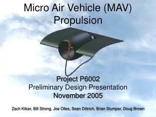
Introduction • Integrate an electric ducted fan into the fuselage of a Micro Air Vehicle (MAV) • Focus on: • Fuselage design • Air Flow Inlet/Duct design • Integrating electronics and fan into the fuselage • Constraints: • 10 lb max • 6 in diameter • 32 in length
EDF VS Propeller fan • Duct reduces losses in thrust caused by tip vortices • The Ducted fan operated at higher velocity • EDF has a smaller diameter • EDFs are quieter and safer
Final Component Selection 76mm ID, 80mm OD 22.2V 391g 55A $129.50 TP8000-6S4PL 22.2V 8000mAh 16C $509.99 Smart Guide ESC Up to 44.4V 100A $120.00
IE Update • Lean Six Sigma Methodology • DMAIC process • Define Phase Complete • Measure Phase due November 30th • Define performance standards • Establish data collection plan • Validate the measurement system • Collect necessary data from existing system
Values Calculated • Maximum Thrust of 2.2 kg =21.6 N • Ideal Inlet Area= 5.643 in2 (FSA, Fan Sweep Area) • Ideal Exit Area=4.3 in2 (75% of FSA) • Maximum Velocity Exiting Fan=52.478 m/s
Design 1 • Design specified by sponsor • Intake from the bottom of the MAV
Design 2 • Intake on top and bottom • Laminar flow off top surface
Design 3 • Maximize flow intake • Simple design
Design 4 • Uses two side ducts • Smooth intake of air
Center of Gravity 1.92 in Desired CG Current CG ESC 110g Fan 391g Battery 932g Fuselage 3084g
Conclusion • Four fuselage designs • Initial Calculations and Analysis • Calculated Ideal Inlet and Outlet Areas • Center of Gravity Analysis • Final Component Selection • The team has started work at HPMI
Future Work • Continue work at HPMI • Produce the first mold • Receive Components • Testing in Comsol and wind tunnels • Measurement of Existing Model
References • Hobbypartz.com • Thunderpowerrc.com • Hobbytown.com • “The Calculation and Design of Ducted Fans”.Wattflyer.com • www2.nlr.nl/public/facilities/AVET-Info/Content/UK/PropBlades.html • www.sterndrive.info/400_800_cobra_propellers.html