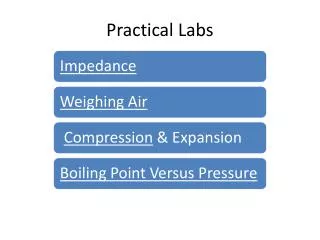
Practical Labs
Practical Labs. Alternating Current Impedance. Three loads wired in series . Alternating Current Impedance. One resistive – a light One capacitive – a capacitor One Inductive – a motor. Alternating Current Impedance. Switches are added in parallel with the capacitor and motor.

Practical Labs
E N D
Presentation Transcript
Alternating Current Impedance Three loads wired in series
Alternating Current Impedance One resistive – a light One capacitive – a capacitor One Inductive – a motor
Alternating Current Impedance Switches are added in parallel with the capacitor and motor. Closing a switch causes current to bypass the load
Resistance Voltage and current are in phase in a resistive circuit. With both switches closed the current bypasses both the inductive and capacitive loads.
Inductance Voltage peaks before current in an inductive circuit. The motor becomes part of the circuit when its switch is opened – adding inductance to the circuit.
Capacitance Voltage peaks after current in a capacitive circuit. The capacitor becomes part of the circuit when its switch is opened adding capacitance to the circuit.
Inductance & Capacitance Voltage and current are in phase in a circuit with capacitance offsetting inductance Both the capacitor and the motor becomes part of the circuit when their switches are opened.
Inductance & Capacitance Click on either switch to change the switch position Back To Menu
Capacitance Click on either switch to change the switch position Back To Menu
Inductance Click on either switch to change the switch position Back To Menu
Resistance Click on either switch to change the switch position Back To Menu
Weighing Air Evacuate Cylinder with Vacuum Pump
Weighing Air Set Scale to Pounds and Ounces 0 lbs 0.0 ozs
Weighing Air Place Evacuated Cylinder on Scale 28 lbs 10.5 ozs
Weighing Air Zero Scale with Tank 0 lbs 0.0 ozs
Weighing Air Open Valve To Let Air In 0 lbs 1.0 ozs Back To Menu
Compression & Expansion Attach Bicycle Pump To Tank
Compression & Expansion Pump Tank Pressure to 40 psig 40 psig
Compression & Expansion Measure Temperature of Line Entering Tank During compression 100°F
Compression & Expansion Close Valve on Tank and Let Tank Sit for 10 Minutes Wait 10 Minutes
Compression & Expansion Open Valve on Tank and Measure Temperature at Valve Outlet 60°F Outlet Air Back To Menu
Boiling Point Versus Pressure Open Valve on Tank and Measure Temperature at Valve Outlet Put water in flask.
Boiling Point Versus Pressure Open Valve on Tank and Measure Temperature at Valve Outlet Stopper flask and connect hose from flask side port to vacuum pump.
Boiling Point Versus Pressure Open Valve on Tank and Measure Temperature at Valve Outlet Start vacuum pump and water boils. Back To Menu