Dependent Sources
Dependent Sources. in Cadence/OrCAD PSpice. Objective of Lecture. Introduce the parts in PSpice for dependent voltage and current sources. Describe how to set the part properties to set the coefficient a for the dependent source.


Dependent Sources
E N D
Presentation Transcript
Dependent Sources in Cadence/OrCAD PSpice
Objective of Lecture • Introduce the parts in PSpice for dependent voltage and current sources. • Describe how to set the part properties to set the coefficient a for the dependent source. • Explain some issues that arise when connecting these parts in the schematics layout tool in PSpice.
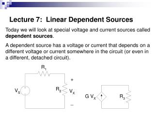
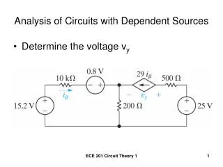
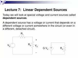
Dependent Sources where a is a cofficient and I and V are the current and voltage at some other point in the circuit.
CCCS Implementation in PSpice
Part F • Double click on F to set the value of the coefficient (a = 3 in this example) that is multiplied by the current through R1 to set the current through the dependent current source.
Layout Issues Wrong: The dependent current source will act as a short across R1 Correct: The current that flows through R1 enters the dependent current source.
Layout Issues • To implement the circuit exactly in PSpice, the wires to Part F had to criss-cross each other on the input and output terminals in order to get the direction of the arrows to follow the direction of the currents in the original circuit.
Layout Issues Both of the wires were extended out laterally from Part F before running one across the other wire. If this was not done, a connection between the terminal on Part F would have been automatically made. A node – dot – would show up on the circuit schematic), creating a short between the two wires. Node created by criss-crossing wires
Layout Issues • To minimize running wires like this, you can change the orientation of the part in the circuit. • Keystroke shortcuts in OrCAD PSpice • Cnt-R is Rotate • Cnt-F is Flip • Cnt-M is Mirror
Layout Issues Original layout After rotating and flipping Part F.
Layout Issues • Alternatively, you can changed the sign on the coefficient, F, on Part F to eliminate one of the criss-crossing connections.
VCVS Implementation in PSpice The connections for the reference voltage used to set the voltage controlled voltage source are made across the component with the sides on the part matching the signs for VR on the circuit.
CCVS Implementation in PSpice
VCCS Implementation in PSpice Changing the sign on the coefficient of the reference voltage in Part G eliminated the need to criss-cross wires on the current source side of the VCCS.
Summary • The names of the parts in PSpice that are dependent sources have been identified and the way to modify the coefficient a was demonstrated. • VCVS: Part E • CCCS: Part F • VCCS: Part G • CCVS: Part H • The control portion of the part is incorporated into the circuit in the same manner that a voltage or current measurement is made using a digital multimeter.