Download
1 / 33
370 likes | 712 Views
ENS 207 engineering graphics. Lecture 4: Orthographic projections, Multiview drawing. The projection theory is used to graphically represent 3-D objects on 2-D media (paper, computer screen). The projection theory is based on two variables: 1) Line of sight

E N D
ENS 207 engineering graphics Lecture 4: Orthographic projections, Multiview drawing
The projection theory is used to graphically represent 3-D objects on 2-D media (paper, computer screen). The projection theory is based on two variables: 1) Line of sight 2) Plane of projection (image plane or picture plane) PROJECTION THEORY
MEANING Orthographic projectionis a parallel projection technique in which the parallel lines of sight are perpendicular to the projection plane
There are 2 types of LOS : Line of sight Line of sight Line of sightis an imaginary ray of light between an observer’s eye and an object. parallel converge and Parallel projection Perspective projection
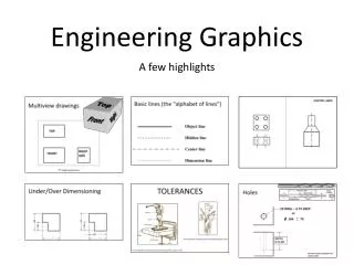
Which Views to Present? • General Guidelines • Pick a Front View that is most descriptive of object • Normally the longest dimension is chosen as the width (or depth) • Most common combination of views is to use: Front, Top, and Side View • Views other than the Principal Views are called Auxiliary Views
TV FV Y X Y X FV TV L G Methods of Drawing Orthographic Projections Third Angle Projections Method Here views are drawn by placing object in 3rd Quadrant. ( Tv above X-y, Fv below X-y) First Angle Projections Method Here views are drawn by placing object in 1st Quadrant ( Fv above X-y, Tv below X-y )
First Versus Third Angle Projection • Third Angle Projection Associated with English units • First Angle Projection Associated with SI units ANSI Symbol
Width Top View Depth Right Side View Front View Height Conventional Orthographic Views AU 2005
Use very light lines for drawing in the construction lines Step 1 – Lightly Block Three Views AU 2005
x y FOR T.V. S.V. F.V. ORTHOGRAPHIC PROJECTIONS FRONT VIEW L.H.SIDE VIEW FOR F.V. FOR S.V. PICTORIAL PRESENTATION IS GIVEN DRAW THREE VIEWS OF THIS OBJECT BY FIRST ANGLE PROJECTION METHOD TOP VIEW
FOR T.V. FOR F.V. X Y FOR S.V. S.V. F.V. ORTHOGRAPHIC PROJECTIONS FRONT VIEW L.H.SIDE VIEW TOP VIEW PICTORIAL PRESENTATION IS GIVEN DRAW THREE VIEWS OF THIS OBJECT BY FIRST ANGLE PROJECTION METHOD
X Y FOR T.V. S.V. F.V. ORTHOGRAPHIC PROJECTIONS L.H.SIDE VIEW FRONT VIEW FOR F.V. FOR S.V. TOP VIEW PICTORIAL PRESENTATION IS GIVEN DRAW THREE VIEWS OF THIS OBJECT BY FIRST ANGLE PROJECTION METHOD
FOR T.V. X Y FOR S.V. FOR F.V. F.V. S.V. ORTHOGRAPHIC PROJECTIONS FRONT VIEW L.H.SIDE VIEW TOP VIEW PICTORIAL PRESENTATION IS GIVEN DRAW THREE VIEWS OF THIS OBJECT BY FIRST ANGLE PROJECTION METHOD
FOR T.V. X Y FOR S.V. FOR F.V. S.V. F.V. ORTHOGRAPHIC PROJECTIONS FRONT VIEW L.H.SIDE VIEW TOP VIEW PICTORIAL PRESENTATION IS GIVEN DRAW THREE VIEWS OF THIS OBJECT BY FIRST ANGLE PROJECTION METHOD
FOR T.V. X Y FOR S.V. FOR F.V. ORTHOGRAPHIC PROJECTIONS FRONT VIEW L.H.SIDE VIEW TOP VIEW PICTORIAL PRESENTATION IS GIVEN DRAW THREE VIEWS OF THIS OBJECT BY FIRST ANGLE PROJECTION METHOD
FOR T.V. 450 30 FV 40 X Y FOR F.V. 30 D TV 40 15 40 O ORTHOGRAPHIC PROJECTIONS PICTORIAL PRESENTATION IS GIVEN DRAW FV AND TV OF THIS OBJECT BY FIRST ANGLE PROJECTION METHOD
FOR T.V. 30 FV RECT. SLOT 10 50 35 10 Y X 20 D FOR F.V. TV 60 D 30 D O PICTORIAL PRESENTATION IS GIVEN DRAW FV AND TV OF THIS OBJECT BY FIRST ANGLE PROJECTION METHOD ORTHOGRAPHIC PROJECTIONS TOP VIEW
HIDDEN LINES Hidden lines are used to represent surfaces that are not directly visible in an orthographic view.
SLANTED SURFACES Slanted surfaces are surfaces that are not parallel to either the horizontal or vertical axis.
COMPOUND LINES A compound line is formed when two slanted surfaces intersect. The true length of a compound line is not shown in the front, top, or side views.
OBLIQUE SURFACES Oblique surfaces are surfaces that do not appear correctly shaped in the front, top, or side views
ROUNDED SURFACES Rounded surfaces are surfaces that have constant radii, such as arcs or circles. Surfaces that do not have constant radii are classified as irregular surfaces
CASTINGS Casting is one of the oldest manufacturing processes. Metal is heated to liquid form, then poured into molds and allowed to cool. The resulting shapes usually include many rounded edges and surface tangencies