Download
1 / 35
350 likes | 521 Views
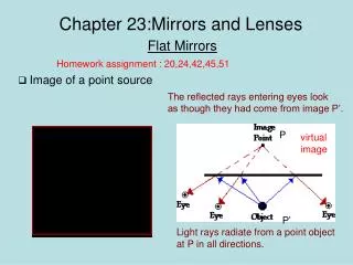
Light , Lenses and Mirrors. W. Sautter 2007. Refraction of Light. Normal Line. i = angle of incidence. r = angle of refraction. i. Air n =1.0. i. Glass n = 1.5. r. Light travels more slowly in glass than air and bends towards the normal when entering glass from air.

E N D
Light , Lenses and Mirrors W. Sautter 2007
Refraction of Light Normal Line i= angle of incidence r= angle of refraction i Air n =1.0 i Glass n = 1.5 r Light travels more slowly in glass than air and bends towards the normal when entering glass from air Light moving from glass to air increases speed and bends away from the normal r Normal Line
Diverging Lens (Double Concave) Virtual focus Focus = - Can form only virtual, Erect and reduced images
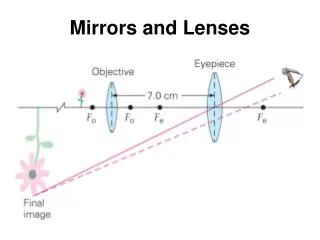
Converging Lens (Double Convex) Principle focus Parallel rays Focus = + Can form real images (enlarged or reduced & inverted) or Enlarged virtual images
Law of Reflection (Angle of Incidence = Angle Reflection) Normal Line Incident ray Reflected ray r i Mirror surface Angles are ALWAYS measured from the NORMAL LINE
Concave Mirrors (Converging Mirrors) Real Focus Parallel rays Focal length = + Forms real, inverted, Reduced or enlarged Image. Also forms Virtual, erect, Enlarged images. Reflected rays
Convex Mirrors (Diverging Mirrors) Virtual focus Parallel rays Focal length = - Forms only virtual, erect, reduced images between the virtual focus and the mirror. Reflected rays
Interference of Waves Destructive interference Constructive interference Waves from a Distant source = crest = trough In phase waves Emerge from slits Barrier with Two slits
Frequency Wavelength Velocity v x = Properties of Transverse Waves Frequency Wavelength Velocity
VISIBLE AND INVISIBLE LIGHT • MOST “LIGHT” IS NOT VISIBLE TO THE HUMAN EYE ! • ONLY ABOUT 7 % OF THE KNOWN KINDS OF LIGHT CAN BE SEEN WITHOUT SPECIAL INSTRUMENTATION.
THE PHOTOELECTRIC EFFECT EXPERIMENT ONLY CERTAIN MINIMUM FREQUENCIES OF LIGHT FREE THE ELECTRONS FROM THE METAL (ONLY PHOTONS WITH ENOUGH ENERGY) PHOTONS VOLTMETER PICKUP WIRE ELECTRONS BATTERY POTASSIUM METAL
Ray Diagrams for Mirrors Parallel ray Focal ray Ray thru 2f 2 f Principal axis focus (f) vertex Reflects parallel To principal axis Reflects Back Into itself Reflects thru The focus
Image is: Real Inverted Reduced Appears between f & 2f Concave Mirror Object Beyond 2f Object beyond 2f Parallel ray Focal ray Ray thru 2f 2 f f
Image is: Real Inverted Same size Appears at 2f Concave Mirror Object at 2f Object at 2f Parallel ray Focal ray ray thru 2f 2 f f
Image is: Real Inverted Enlarged Appears beyond 2f Concave Mirror Object Between f & 2f Object between f and 2f Parallel ray 2 f f ray thru 2f Focal ray
Apparent Convergence Of rays Image is: Virtual Erect Enlarged Appears behind the mirror Concave Mirror Object Between f & Vertex Parallel ray Focal ray ray thru 2f 2 f f ray thru 2f Object inside focus
Reflections from a Plane Mirror Dotted lines Shows the Apparent Ray source Angle of incidence = Angle of Reflection For each ray
Image in a Convex Mirror Virtual focus Dotted lines Shows the Apparent Ray focus Parallel rays Focal length = - Forms only virtual, erect, reduced images between the virtual focus and the mirror. Reflected rays
Image in a Convex Mirror Image is: Virtual Erect Reduced Appears behind the mirror Apparent Convergence of rays Parallel ray Ray thru 2f Focal ray (f) 2 f
focus (f) 2 f focus (f) 2 f x x x x Rays Diagrams for Converging Lens (Double Convex) A ray thru the Center of the lenses Parallel ray Passes thru The focus Remains unbent Focal ray Refracts parallel To principal axis
Object Beyond 2f Converging Lens (Double Convex) focus (f) 2 f focus (f) 2 f x x x x Image is: Real Inverted Reduced Appears between f and 2f Parallel ray Focal ray Object beyond 2f
Object at 2f Converging Lens (Double Convex) focus (f) 2 f focus (f) 2 f x x x x Image is: Real Inverted Same size Appears between f and 2f Parallel ray Focal ray Object at 2f
focus (f) 2 f focus (f) 2 f x x x x Object Between 2f & fConverging Lens (Double Convex) Image is: Real Inverted Enlarged Appears beyond 2f Parallel ray Focal ray Object between f and 2f
Apparent Convergence Of rays focus (f) 2 f focus (f) 2 f x x x x Object Between f & Mirror Converging Lens (Double Convex) Image is: Virtual Erect Enlarged Appears on same Side as Object Object Inside focus
Rays Diagrams for Diverging Lens (Double Convcave) focus (f) focus (f) 2 f 2 f Apparent ray convergence Is on same side as object
Rays Diagrams for Diverging Lens (Double Convcave) Parallel ray Focal ray f f 2 f 2 f Ray thru center Image is: Virtual Erect Reduced Appears on same Side as object
Wave B Wave A Wave B Wave A Wave B Wave A Interference of Waves Constructive interference Destructive interference Partially Constructive interference
Double Slit Diffraction Interference of Waves Destructive interference Constructive interference Waves from a Distant source = crest = trough In phase waves Emerge from slits Barrier with Two slits
Single Slit Diffraction Patterns Double Slit Diffraction Patterns
m = d sin Interference of Waves Double Slit Diffraction
Diffraction Variables 2 m S P E C T R A L O R D E R 1 d 0 1 2
Double Slit Diffraction Variables • m = spectral order • The bright central band is zero and each bright band • to the right or left is counted by consecutive • integers 1,2,3 etc. • d = distance separating the slits (meters) • = wavelength of light in meters = angle between the zero band and the spectral band m
Single Slit Diffraction Each edge of the slit creates a new wave front. The two new waves then interfer creating a diffraction pattern
Single Slit Diffraction m = s sin • m = spectral order • The bright central band is zero and each dark band • to the right or left is counted by consecutive • integers 1,2,3 etc. • s= slit width (meters) • = wavelength of light in meters = angle between the zero band and the spectral band m