Download
1 / 1
10 likes | 108 Views
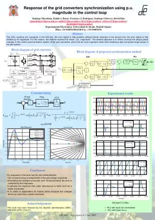
Comparison of two sPLL systems for grid converter synchronization with a focus on reflecting abrupt phase changes accurately. The proposed method, "p.u. magnitude," aims to improve control under unbalance dips and phase-angle jumps. Features constant tuning, faster response time, and lesser overshoots. Useful for motor drives. Includes block diagrams and experimental results.

E N D
PLL DSC Filtro PI VCO 0 ‘delay’ -1 L1 ea(t) ua(t) L1 eb(t) ub(t) Cdc udc L1 ec(t) uc(t) pulses uDC meas. PWM generator Current meas. Grid voltage meas. DC control Current control Response of the grid converters synchronization using p.u. magnitude in the control loop Santiago Muyulema, Emilio J. Bueno, Francisco J. Rodríguez, Santiago Cóbreces, David Díaz smuyulema@depeca.uah.es; emilio@depeca.uah.es; fjrs@depeca.uah.es; cobreces@depeca.uah.es; david.diaz@depeca.uah.es Departamento Electrónica. Universidad de Alcalá. Madrid (Spain) Tlfno. +34 918856584/6540 Fax. +34 918856591 Abstract Two sPLL systems are compared: in the first one, the error signal is Vdp (positive refence frame); whereas in the second one, the error signal is Vdp divided by its magnitude. For this reason, the method receives the name: “p.u. magnitude”. The desired objective is to reflect correctly the abrupt phase changes in the control synchronization system of the grid converters, which will be more important under hard unbalance dips and phase-angle jumps in the grid system. Block diagram of grid converter Block diagram of proposed synchronization method Constant tuning Experimental results ωn=2π100 Conclusions • PLL proposed in this work has the next characteristics: • The constant tuning is independent of the grid voltage magnitude. • Eliminating the constant systematic error introduced when the error is multiplied by the magnitude. • In general, the response time under disturbances is faster and has a lesser overshoots. • It is useful in applications for motors drives because the voltages which are used have variable amplitude. • Dip type D 0.25pu. • PLL with input non normalized • PLL with input in p.u. Acknowledgements This work has been financed by the Spanish administration (MEC: ENE2005-08721-C04-01). ISIE 2007 - Vigo (Spain) 4-7 June 2007