Download
1 / 5
70 likes | 86 Views
ASTM A334/A334M is a standard specification for seamless and welded carbon and alloy steel tubes. It covers material up to 1 inch in thickness, with chemical and mechanical properties suitable for low temperature service. It has excellent impact strength at subzero temperatures, making it ideal for cold weather applications such as cryogenic storage tanks. The tubing is commonly used in oil and gas production lines, pressure vessels, piping systems, boilers, heat exchangers and other parts exposed to extreme temperatures.

E N D
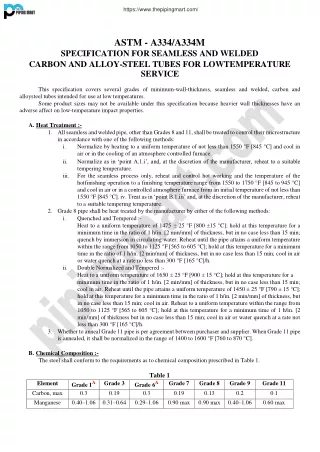
https://www.thepipingmart.com/ ASTM - A334/A334M SPECIFICATION FOR SEAMLESS AND WELDED CARBON AND ALLOY-STEEL TUBES FOR LOWTEMPERATURE SERVICE This specification covers several grades of minimum-wall-thickness, seamless and welded, carbon and alloysteel tubes intended for use at low temperatures. Some product sizes may not be available under this specification because heavier wall thicknesses have an adverse affect on low-temperature impact properties. A.Heat Treatment :- 1.All seamless and welded pipe, other than Grades 8 and 11, shall be treated to control their microstructure in accordance with one of the following methods: i. Normalize by heating to a uniform temperature of not less than 1550 °F [845 °C] and cool in air or in the cooling of an atmosphere controlled furnace. ii. Normalize as in ‘point A.1.i’, and, at the discretion of the manufacturer, reheat to a suitable tempering temperature. iii. For the seamless process only, reheat and control hot working and the temperature of the hotfinishing operation to a finishing temperature range from 1550 to 1750 °F [845 to 945 °C] and cool in air or in a controlled atmosphere furnace from an initial temperature of not less than 1550 °F [845 °C]. iv.Treat as in ‘point B.1.iii’ and, at the discretion of the manufacturer, reheat to a suitable tempering temperature. 2.Grade 8 pipe shall be heat treated by the manufacturer by either of the following methods: i. Quenched and Tempered :- Heat to a uniform temperature of 1475 ± 25 °F [800 ±15 °C]; hold at this temperature for a minimum time in the ratio of 1 h/in. [2 min/mm] of thickness, but in no case less than 15 min; quench by immersion in circulating water. Reheat until the pipe attains a uniform temperature within the range from 1050 to 1125 °F [565 to 605 °C]; hold at this temperature for a minimum time in the ratio of 1 h/in. [2 min/mm] of thickness, but in no case less than 15 min; cool in air or water quench at a rate no less than 300 °F [165 °C]/h. ii. Double Normalized and Tempered :- Heat to a uniform temperature of 1650 ± 25 °F [900 ± 15 °C]; hold at this temperature for a minimum time in the ratio of 1 h/in. [2 min/mm] of thickness, but in no case less than 15 min; cool in air. Reheat until the pipe attains a uniform temperature of 1450 ± 25 °F [790 ± 15 °C]; hold at this temperature for a minimum time in the ratio of 1 h/in. [2 min/mm] of thickness, but in no case less than 15 min; cool in air. Reheat to a uniform temperature within the range from 1050 to 1125 °F [565 to 605 °C]; hold at this temperature for a minimum time of 1 h/in. [2 min/mm] of thickness but in no case less than 15 min; cool in air or water quench at a rate not less than 300 °F [165 °C]/h. 3.Whether to anneal Grade 11 pipe is per agreement between purchaser and supplier. When Grade 11 pipe is annealed, it shall be normalized in the range of 1400 to 1600 °F [760 to 870 °C]. B.Chemical Composition :- The steel shall conform to the requirements as to chemical composition prescribed in Table 1. Table 1 Element Grade 1A Grade 3 Grade 6A Carbon, max 0.3 0.19 0.3 Manganese 0.40–1.06 0.31–0.64 0.29–1.06 Grade 7 0.19 0.90 max Grade 8 0.13 0.90 max 0.40–1.06 Grade 9 0.2 Grade 11 0.1 0.60 max
Phosphorus, max Sulfur, max Silicon Nickel Chromium Copper Cobalt Molybdenum 0.025 0.025 0.025 0.025 0.025 0.025 0.025 0.025 ... ... ... ... ... ... 0.025 0.18–0.37 3.18–3.82 ... ... ... ... 0.025 0.10 min ... ... ... ... ... 0.025 0.13–0.32 0.13–0.32 2.03–2.57 8.40–9.60 1.60–2.24 ... ... ... ... ... ... ... ... 0.025 0.025 ... 0.025 0.35 max 35.0–37.0 0.50 max ... 0.50 max 0.50 max ... 0.75–1.25 ... ... A For each reduction of 0.01% carbon below 0.30%, an increase of 0.05% manganese above 1.06% will be permitted to a maximum of 1.35% manganese. C.Tensile Requirements :- The material shall conform to the requirements as to tensile properties prescribed in Table 2. Table 2 Grade 1 Grade 3 Grade 6 Grade 7 Grade 8 Grade 9 Grade 11 ksi MPa ksi MPa ksi MPa ksi MPa ksi MPa ksi MPa ksi MPa Tensile Strength, min 55 380 65 450 60 415 65 450 100 690 63 435 65 450 Yield Strength, min 30 205 35 240 35 240 35 240 75 520 46 315 35 240 Elongation in 2 in. or 50 mm (or 4D), min, %: Basic minimum elongation for walls 5⁄16 in. [8 mm] and over in thickness, strip tests, and for all small sizes tested in full section When standard round 2 in. or 50 mm gage length or proportionally smaller size specimen with the gage length equal to 4D (4 times the diameter) is used For strip tests, a deduction for each 1⁄32 in. [0.8 mm] decrease in wall thick-ness below 5⁄16 in. [8 mm] from the basic minimum elongation of the following percentage points AElongation of Grade 11 is for all walls and for small sizes tested in full section. BThe following table gives the calculated minimum values: 18A 35 30 30 30 22 28 28 22 22 22 16 … … 1.75B 1.50B 1.50B 1.50B 1.25B 1.50B … 5⁄16 (0.312) 8 9⁄32 (0.281) 7.2 1⁄4 7⁄32 (0.219) 5.6 3⁄16 (0.188) 4.8 5⁄32 (0.156) 4 1⁄8 3⁄32 (0.094) 2.4 1⁄16 (0.062) 1.6 in. (0.250) 6.4 (0.125) 3.2 Wall Thickness mm Grade 1 35 33 32 30 28 26 25 23 21 Grade 3 30 28 27 26 24 22 21 20 18 Elongation in 2 in. or 50 mm, min, %A Grade 6 30 28 27 26 24 22 21 20 18 Grade 7 30 28 27 26 24 22 21 20 18 https://www.thepipingmart.com/
Grade 8 22 21 20 18 17 16 15 13 12 Grade 9 28 26 25 24 22 20 19 18 16 ACalculated elongation requirements shall be rounded to the nearest whole number. NOTE: The above table gives the computed minimum elongation values for each 1⁄32 in. [0.8 mm] decrease in wall thickness. Where the wall thickness lies between two values shown above, the minimum elongation value is determined by the following equations. Grade 1 E = 56t + 17.50 [E = 2.19t + 17.50] 3 E = 48t + 15.00 [E = 1.87t + 15.00] 6 E = 48t + 15.00 [E = 1.87t + 15.00] 7 E = 48t + 15.00 [E = 1.87t + 15.00] 8 E = 40t + 9.50 [E = 1.56t + 9.50] 9 E = 48t + 13.00 [E = 1.87t + 13.00] where: E = elongation in 2 in. or 50 mm, %, and t = actual thickness of specimen, in. [mm ]. D.Hardness Requirements :- The tubes shall have a hardness number not exceeding those prescribed in Table 3. Table Equation 3 Grade 1 3 6 7 8 11 Rockwell B 85 B 90 B 90 B 90 ... B 90 Brinell 163 190 190 190 ... 190 E.Impact Requirements :- 1.For Grades 1, 3, 6, 7 and 9, the notched-bar impact properties of each set of three impact specimens, including specimens for the welded joint in welded pipe with wall thicknesses of 0.120 in. [3 mm] and larger, when tested at temperatures in conformance with ‘point H.1’ shall be not less than the values prescribed in Table 4. 2.The impact test is not required for Grade 11. 3.For Grade 8 each of the notched bar impact specimens shall display a lateral expansion opposite the notch of not less than 0.015 in. [0.38 mm]. 4.When the average lateral expansion value for the three impact specimens equals or exceeds 0.015 in. [0.38 mm] and the value for one specimen is below 0.015 in. [0.38 mm] but not below 0.010 in. [0.25 mm], a retest of three additional specimens may be made. The lateral expansion of each of the retest specimens must equal or exceed 0.015 in. [0.38 mm]. Table 4 Size of Specimen, mm ft·lbf J 10 by 10 13 18 10 by 7.5 10 14 10 by 6.67 9 12 10 by 5 7 9 Minimum Average Notched Bar Impact Value of Each Set of Three SpecimensA Minimum Notched Bar Impact Value of One Specimen Only of a SetA ft·lbf 10 8 7 5 J 14 11 9 7 https://www.thepipingmart.com/
10 by 3.33 10 by 2.5 A Straight line interpolation for intermediate values is permitted. F.Mechanical Testing :- 1.Tension Test. 2.Flattening Test. 3.Flare Test (Seamless Tubes). 4.Flange Test (Welded Tubes). 5.Reverse Flattening Test. 6.Hardness Test. 7.Impact Tests. 8.Impact Tests (Welded Tubes). G.Specimens for Impact Test:- 1.Notched bar impact specimens shall be of the simple beam, Charpy-type, in accordance with Test Methods E23, Type A with a V notch. H.Impact Test :- 1.Except when the size of the finished pipe is insufficient to permit obtaining subsize impact specimens, all material furnished underthis specification shall be tested for impact resistance at the minimum temperature for the respective grades as shown in Table 5. 2.When subsize Charpy impact specimens are used and the width along the notch is less than 80 % of the actual wall thickness of the original material, the specified Charpy impact test temperature for Grades 1, 3, 4, 6, 7 and 9 shall be lower than the minimum temperature shown in Table 5 for the respective grade. Under these circumstances the temperature reduction values shall be by an amount equal to the difference (as shown in Table 6) between the temperature reduction corresponding to the actual material thickness and the temperature reduction corresponding to the Charpy specimen width actually tested. 3.The notched bar impact test shall be made in accordance with the procedure for the simple beam, Charpy-type test of Test Methods E23. 4.Impact tests specified for temperatures lower than 70 °F [20 °C] should be made with the following precautions :- i. The impact test specimens as well as the handling tongs shall be cooled a sufficient time in a suitable container so that both reach the desired temperature. ii. The temperature shall be measured with thermocouples, thermometers, or any other suitable devices and shall be controlled within ± 3 °F [2 °C]. iii. The specimens shall be quickly transferred from the cooling device to the anvil of the Charpy impact testing machine and broken with a time lapse of not more than 5 s. Table 5 Minimum Impact Test Temperature °F 1 −50 3 −150 6 −50 7 −100 8 −320 9 −100 Table 6 Specimen Width Along Notch or Actual Material Thickness 5 4 7 5 3 3 4 4 Grade °C −45 −100 −45 −75 −195 −75 Temperature Reduction, Degrees ColderA https://www.thepipingmart.com/
in. 0.394 0.354 0.315 0.295 0.276 0.262 0.236 0.197 0.158 0.131 0.118 0.099 mm °F 0 0 0 5 8 10 15 20 30 35 40 50 °C 0 0 0 3 4 5 8 11 17 19 22 28 10 ( standard size) 9 8 7.5 (3⁄4 std. size) 7 6.67 (2⁄3 std. size) 6 5 (1⁄2 std. size) 4 3.33 (1⁄3 std. size) 3 2.5 (1⁄4 std. size) A Straight line interpolation for intermediate values is permitted. I.Hydrostatic or Non-destructive Electric Test :- 1.The type of test to be used shall be at the option of the manufacturer, unless otherwise specified in the purchase order. 2.Each tube shall be subjected to the non-destructive electric test or the hydrostatic test in accordance with Specification A 1016/A 1016M. Keyword • astm a334 pdf • astm a334 specification • astm a334 grade 6 • sa334 pdf free download • sa334 pdf download • sa334 gr 1 https://www.thepipingmart.com/