Download
1 / 65
970 likes | 1.49k Views
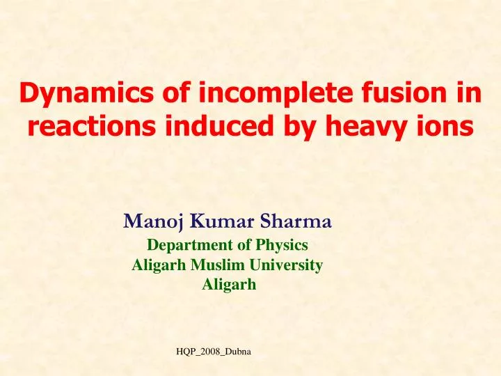
Dynamics of incomplete fusion in reactions induced by heavy ions. Manoj Kumar Sharma Department of Physics Aligarh Muslim University Aligarh. Introduction Scientific Motivation Experimental details Analysis of the data Conclusions. Residual nucleus. Incident ion. . +. Ejectile.

E N D
Dynamics of incomplete fusion in reactions induced by heavy ions Manoj Kumar Sharma Department of Physics Aligarh Muslim University Aligarh HQP_2008_Dubna
Introduction Scientific Motivation Experimental details Analysis of the data Conclusions HQP_2008_Dubna
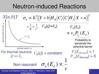
Residual nucleus Incident ion + Ejectile Target nucleus Introduction A nuclear reaction takes place, when an incident ion of sufficient energy (above the Coulomb barrier) interacts with a target nucleus. a + X Y + b Where, a-projectile , X-target Y-residual nucleus, b-emitted particle HQP_2008_Dubna
Complete fusion b b Impact parameter Elastic scattering Direct reactions Peripheral collision Incomplete fusion and deep inelastic collision Grazing collision Distant collision Rutherford Scattering A pictorial representation of heavy ion reactions HQP_2008_Dubna
In heavy ion reactions, at moderate excitation energies, the dominant processes are; • Complete Fusion (CF) • Incomplete Fusion (ICF) • Pre-equilibrium (PE) emission HQP_2008_Dubna
Ta174 n p + 73Ta175 Hf174 8O16 65Tb159 Composite system Projectile Target Lu171 Complete Fusion (CF) Projectile is completely fused with the target nucleus, leading to the formation of an excited composite system that may decay by the emission of n, p, etc., after attaining statistical equilibrium. HQP_2008_Dubna
Lu170 n 6C12 p + 71Lu171 Yb170 65Tb159 Composite system Projectile Target Er167 Residues Incomplete Fusion (ICF) Only a part of the projectile fuses with the target nucleus and the rest of it is going into the beam direction with almost the same velocity as that of incident ion beam. 16O=12C+ HQP_2008_Dubna
Some of the important features of ICF…… • Higher measured cross-sections than predicted by statistical models, M. K. Sharma et. at., Phys. Rev. C70 (2004) 044606 HQP_2008_Dubna
Fractional momentum transfer, in which the residue formed as a result of ICF of projectile travels to a lower range in a given medium. Incomplete Momentum Transfer M. K. Sharma et. at., Phys. Rev. C70, (2004) 044606 HQP_2008_Dubna
ICF reactions have attracted attention…….. • The threshold for ICF is not well established. • Early studies show occurrence of ICF at higher energies above 10 MeV/nucleon • Recent experimental studies have shown that ICF starts competing with CF even at energies around 5-7 MeV/nucleon i.e, just above the Coulomb barrier. HQP_2008_Dubna
Why?......... • Relative contributions of CF and ICF are not well known. • The dynamics of ICF is not well understood at energies around 5-7 MeV/A. • Energy dependence of CF and ICF contributions is not well understood. • No satisfactory theory for ICF is available. • Limited studies are available at <10 MeV/A. HQP_2008_Dubna
In order to answer some of these, measurements of…….. • Excitation functions covering a large range of energy, • Recoil range distributions at several energies, • Angular distributions of the residues, • Spin distribution of the residues HQP_2008_Dubna
In the present work, Excitation functions (EFs) for the following systems have been studied; • 12C+27Al39K, Coulomb barrier 24 MeV • Beam energy (42 to 82 MeV) • 16O+27Al 43Sc, Coulomb barrier 27 MeV • Beam energy (55 to 95 MeV) • 14N+128Te 142Pr, Coulomb barrier 58 MeV • Beam energy (64 to 90 MeV) • 16O+130Te 146Nd, Coulomb barrier 53 MeV • Beam energy (42 to 82 MeV) • 16O+103Rh 119I, Coulomb barrier 48 MeV • Beam energy (48 to 90 MeV) • 16O+159Tb 175Ta , Coulomb barrier 66 MeV • Beam energy (70 to 95 MeV) • 16O+169Tm 185Ir, Coulomb barrier 68 MeV • Beam energy (70 to 95MeV) HQP_2008_Dubna
27Al(12C,n)34Cl, 27Al(12C,23p)28Mg, 27Al(12C,32pn)24Na, 27Al(16O,2n)34Cl, 27Al(16O,33p)28Mg, 27Al(16O,33pn)27Mg, 27Al(16O,42pn)24Na, 27Al(16O,43p)24Ne, 128Te(16O,4n)138Pr, 128Te(16O,5n)137Pr, 128Te(16O,p4n)137Ce, 128Te(16O, 5n)133La, 128Te(16O, 6n)132La, 128Te(16O, 2pn)135La, 128Te(16O, 22pn)131I, 128Te(16O, 3)130I, 103Rh(16O,pn)117Te, 103Rh(16O,p2n)116Te, 103Rh(16O,p3n)115Te, 103Rh(16O,p4n)114Te, 103Rh(16O,2n)117Sb, 103Rh(16O,2pn)116Sb, 103Rh(16O,2p2n)115Sb, 103Rh(16O,p4n)110Sn, 103Rh(16O,2)111In, 103Rh(16O,2n)110In, 103Rh(16O,22n)109In, 103Rh(16O,23n)108In, 103Rh(16O,3n)106Ag, 103Rh(16O,33n)104Ag, 103Rh(16O,34n)103Ag, 159Tb(16O,3n)172Ta, 159Tb(16O,4n)171Ta, 159Tb(16O,5n)170Ta, 159Tb(16O,p3n)171Lu, 159Tb(16O,p4n)170Lu, 159Tb(16O,)172Hf, 159Tb(16O,n)170Hf, 159Tb(16O,2n)169Hf, 159Tb(16O,3n)168Hf, 159Tb(16O,4n)167Hf, 159Tb(16O,p3n)167Lu, 159Tb(16O,2n)166Tm, 159Tb(16O,22n)165Tm, 169Tm(16O,3n)182Ir, 169Tm(16O,4n)181Ir, 169Tm(16O,p2n)182Os, 169Tm(16O,p3n)181Os, 169Tm(16O,)181Re, 169Tm(16O,2n)179Re, 169Tm(16O,3n)178Re, 169Tm(16O,4n)177Re, 169Tm(16O,p3n)177W, 169Tm(16O,2pn)178Ta, 169Tm(16O,3pn)177Hf 169Tm(16O,2p3n)172Hf ,169Tm(16O,3n)172Lu HQP_2008_Dubna
Methodology adopted The experiments have been carried out using the Pelletron accelerator facility of the Inter University Accelerator Facilities (IUAC) (Formerly known as NSC), New Delhi, INDIA. Samples preparation: 27Al (Rolling Method) 103Rh (Rolling Method) 128,130Te (Vacuum evaporation) 159Tb (Rolling Method) 169Tm(Vacuum evaporation) HQP_2008_Dubna
Thickness measurements • The thickness of each target was determined by the -transmission method. • 27Al2.00 mg/cm2 • 103Rh 1.80 mg/cm2 • 128Te (66%)0.90 mg/cm2 • 130Te (68%) 1.00 mg/cm2 • 159Tb 1.80 mg/cm2 • 169Tm 0.50 mg/cm2 HQP_2008_Dubna
Al-Catcher foil/ Energy degreder Target Incident beam A typical stack arrangement for the measurement of EFs HQP_2008_Dubna
Catcher Faraday cup Incident beam Target Irradiation The irradiations were carried out in the General Purpose Scattering Chamber (GPSC) having in-vacuum transfer facility. A typical experimental set up for the measurement of EFs HQP_2008_Dubna
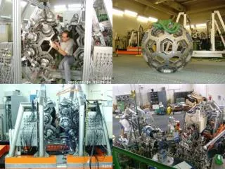
General Purpose Scattering Chamber ITF HQP_2008_Dubna
Inside view of GPSC Upper arm Lower arm HQP_2008_Dubna
Invacuum Transfer Facility • The delay time between stop the irradiation and beginning of the counting may be minimized. • Target may be replaced without disturbing the vacuum inside the chamber. Pirani gauge Valve-I Port for rotary pump Valve-II HQP_2008_Dubna
Post Irradiation Analysis The samples were taken out from the scattering chamber and activities induced in the samples were analyzed using HPGe detector. The detector was pre-calibrated using various standard sources i.e., 22Na, 60Co, 133Ba, 137Cs, 152 Eu etc., INCIDENT BEAM HQP_2008_Dubna
M. K. Sharma et. al., Nucl. Phys. A 776, 2006 (84) A typical geometry dependent efficiency curves for various source detector distances as a function of -ray energy is shown. HQP_2008_Dubna
M. K. Sharma et. al., Phys. Rev. C 75 (2007)044608 M. K. Sharma et al., Phys. Rev. C 70 (2004)044604 The observed -rays spectrum for 16O+27Al and 16O+159Tb systems HQP_2008_Dubna
M. K. Sharma et al., Nucl. Phys. A776 (2006)84 The observed -rays spectrum for 16O+159Tb system at 95 MeV HQP_2008_Dubna
The intensity of these -rays are used to measure the reaction cross-section using following formulation. where, A is the total observed counts during the accumulation time t3 of the induced activity of decay constant , No the number of target nuclei irradiated for time t1 with a particle beam of flux , t2 the time lapse between the stop of irradiation and the start of counting, the branching ratio of the characteristic -ray and Gthe geometry dependent efficiency of the detector. The factor [1-exp (t1)] takes care of the decay of evaporation residue during the irradiation and is typically known as the saturation correction. HQP_2008_Dubna
Analysis Analysis of the excitation functions has been done using three different computer codes, HQP_2008_Dubna None of these codes take in account ICF contribution
M. K. Sharma et al., Phys. Rev. C 70 (2004) 044606 Experimentally measured and theoretically calculated EFs HQP_2008_Dubna
M. K. Sharma et. al., Nucl. Phys. A 776 (2006) 86 171Ta 4n + 16O + 159Tb 175Ta p3n 171Hf The residues 171Hf which may be formed via the reaction 159Tb(16O,p3n) and may also be formed by the + decay of higher charge isobar precursor 171Ta produced via the reaction 159Tb(16O,4n). As such, the measured activity of residues 171Hf has contribution from precursor decay also. HQP_2008_Dubna
HQP_2008_Dubna Experimentally measured and theoretically calculated EFs
M. K. Sharma et. al., Nucl. Phys. A 776 (2006)83 HQP_2008_Dubna Experimentally measured and theoretically calculated EFs
M. K. Sharma et. al., Nucl. Phys. A 776 (2006) 83 At higher energies, the calculation of EFs done with code ALICE-91 gives significant contribution from PE-emission also. Experimentally measured and theoretically calculated EFs HQP_2008_Dubna
Experimentally measured and theoretically calculated EFs HQP_2008_Dubna
Experimentally measured and theoretically calculated EFs HQP_2008_Dubna
M. K. Sharma et. al., Nucl. Phys. A 776 (2006)83 HQP_2008_Dubna Experimentally measured and theoretically calculated EFs
M. K. Sharma et. al., Nucl. Phys. A 776 (2006)83 Phys. Rev C 77 (2008)014607 Experimentally measured EFs HQP_2008_Dubna
From the analysis of the excitation functions, enhancement of the cross-sections in comparison to theoretical calculations done using statistical model codes, may be attributed to ICF processes. • Following reactions have been found to have significant contribution from ICF 27Al(16O,2n)34Cl, 27Al(16O,33p)28Mg, 27Al(16O,33pn)27Mg, 27Al(16O,42pn)24Na, 27Al(16O,43p)24Ne, 128Te(16O, 5n)133La, 128Te(16O, 6n)132La, 128Te(16O, 2pn)135La, 128Te(16O, 22pn)131I, 128Te(16O, 3)130I, 103Rh(16O,2p2n)115Sb, 103Rh(16O,p4n)110Sn, 103Rh(16O,2)111In, 103Rh(16O,2n)110In, 103Rh(16O,22n)109In, 103Rh(16O,23n)108In, 103Rh(16O,3n)106Ag, 103Rh(16O,33n)104Ag, 103Rh(16O,34n)103Ag, 159Tb(16O,)172Hf, 159Tb(16O,n)170Hf, 159Tb(16O,2n)169Hf, 159Tb(16O,3n)168Hf, 159Tb(16O,4n)167Hf, 159Tb(16O,p3n)167Lu, 159Tb(16O,2n)166Tm, 159Tb(16O,22n)165Tm, 169Tm(16O,)181Re, 169Tm(16O,2n)179Re, 169Tm(16O,3n)178Re, 169Tm(16O,4n)177Re, 169Tm(16O,p3n)177W, 169Tm(16O,2pn)178Ta, 169Tm(16O,3pn)177Hf 169Tm(16O,2p3n)172Hf ,169Tm(16O,3n)172Lu HQP_2008_Dubna
Phys. Rev C 77 (2008)014607 The Contribution of ICF has been deduced by subtracting the cross-section of CF from total cross-sections. FICF increases with increase in beam energy HQP_2008_Dubna
Mass asymmetry dependence of ICF fraction • ICF is observed in competition with CF in energy range presently studied. • In present systems ICF is found to increase with beam energy. • SCF is found to be large in more mass asymmetric systems as compared to mass symmetric system. • It may however, be pointed out that the results shown here may not be conclusive and more experimental data for a large number of systems may be required to get detailed information about the suppression of CF over ICF. HQP_2008_Dubna
Recoil Range Distributions • The measurement of RRD is based on the linear momentum transfer of the projectile to the target nucleus. • In CF reactions, the linear momentum is completely transferred to the target nucleus, thus the residues formed by CF may be trapped at a larger distance in the stopping medium. • While in case of ICF reactions, partial transfer of projectile momentum takes place thus the residues may be trapped at a shorter distance in the stopping medium . HQP_2008_Dubna
Target foil Thin Al -catcher foils Recoiling Nucleus Incident Beam Experimental Set-up for Recoil Range Distribution measurements HQP_2008_Dubna
In the present work, following systems have been used to measure RRD of the residues. ·16O + 159Tb 175Ta ( 92 MeV ) ·16O + 169Tm 185Ir ( 76, 81 & 87 MeV ) HQP_2008_Dubna
M. K. Sharma et. al., Nucl. Phys. A 776 (2006) 84 Experimental measured Recoil Range Distribution for 16O+159Tb @ 92 MeV HQP_2008_Dubna
M. K. Sharma et. al., Nucl. Phys. A 776 (2006) 84 HQP_2008_Dubna Experimental measured Recoil Range Distribution
Experimental measured Recoil Range Distribution for 16O+169Tm @ 95 MeV HQP_2008_Dubna
M. K. Sharma et. al., Phys. Rev. C 70 (2004) 044606 The experimentally measured RRD has been fitted with Gaussian peaks. The areas under the two peaks have been computed. The relative contributions of the CF and ICF processes are obtained by dividing the area of the individual peak by the total area. 16O+169Tm185Ir* 181Re+2p2n (CF 355%) 12C +169Tm181Re* + + (ICF 655%) HQP_2008_Dubna
Manoj Kumar Sharma et. al., Phys. Rev. C70 (2004)044606 16O+169Tm185Ir* 176Hf+2pn CF 255% 12C +169Tm181Re* 176Hf + pn ICF of 12C 455% 8Be +169Tm178Ta* 176Hf + pn ICF of 8 Be 305% HQP_2008_Dubna
M. K. Sharma et. al., Phys. Rev. C70 (2004)044606 ICF of 8 Be 745% ICF of 265% HQP_2008_Dubna
M. K. Sharma et. al., Phys. Rev. C70 (2004)044606 ICF of 8 Be 285% ICF of 72 5% HQP_2008_Dubna
M. K. Sharma et. al., Nucl. Phys. A 776 (2006) 84 HQP_2008_Dubna