
Introduction
Learn how to monitor and control radiation levels and high voltage in the ZD drift chamber with these step-by-step instructions.

Introduction
E N D
Presentation Transcript
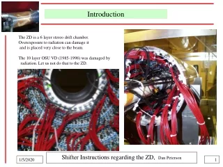
Introduction The ZD is a 6 layer stereo drift chamber. Overexposure to radiation can damage it and is placed very close to the beam. The 10 layer OSU VD (1985-1998) was damaged by radiation. Let us not do that to the ZD. Shifter Instructions regarding the ZD, Dan Peterson
Getting familiar with the CESR display • This is the CESR display. • Look around for it or ask the professional shifter. • There are 3 things to look at: • Radiation monitors • (detectors are on the beam pipe) • “star” plots • 2) ZD layer currents • there are “star” plots • and numerical display (mA) • 3) Beam life time (in minutes) • blue=e-, red=e+ Shifter Instructions regarding the ZD, Dan Peterson
Before starting a run Before starting a run, the beams must be cool enough to not spray radiation all over the ZD. Before ramping the CLEO HV system from “FILL” to “RUN” the beam life time must be more than 50 minutes. Observe the beam lifetime on the CESR display here. Blue is e-, Red is e+. When the CESR operator says “tuning is complete” we are not ready; the HV should not yet be “sync’ed to cesr”. The numbers may be =0 or bouncing. Wait for beam lifetimes to be relatively stable and above 50 minutes. And, that is not all; see next page. Shifter Instructions regarding the ZD, Dan Peterson
Before starting a run, 2 There are 2 “star” plots of the radiation monitors, one for East, one for West. Both should show low radiation. The shape in the center should be collapsed to near zero. The physicist shifter watch this plot to ensure that the radiation level is low before the ramp to “run”. OK BAD Shifter Instructions regarding the ZD, Dan Peterson
The High Voltage GUI The HV GUI display should be displaying current as shown here. The DR3 is all between 4 and 5 mA. The ZD is all between 3 and 4 mA. This is almost all bleeder circuit current, 4.2 mA in the DR and 3.8 mA in the ZD. If the colors do not look like this, it should be noted. The blue channels here are bad supplies; the chambers channels are powered by jumpers to good channels. All is good. This is supply 7-13/14 which powers chamber 7-14. It always trips. Shifter Instructions regarding the ZD, Dan Peterson
High Voltage trips This is the HV trip window. The HV form should be maintained by the professional shifter and the physicist shifter. Write down the trip. Conform to the requested syntax. In this case write “ hour : minute DR 7-13/14 “ Shifter Instructions regarding the ZD, Dan Peterson
CLEO HV telnet windows You may be asked to look at the current levels in the telnet windows. Box 80, channels 9.1.0 - 9.1.7 is ZD layer 1 9.1.8 - 9.1.15 is ZD layer 3 9.1.16 - 9.1.23 is ZD layer 5 Box 81, channels 11.1.0 - 11.1.7 is ZD layer 2 11.1.8 - 11.1.15 is ZD layer 4 11.1.16 - 11.1.23 is ZD layer 6 Box 81, channels 12.1.8 – 12.1.23 are the ZD cathode wire layers, F1- and F6+. Shifter Instructions regarding the ZD, Dan Peterson
CLEO Event Display The full event is usually in a small window. This is a nice endcap Bhabha. Shifter Instructions regarding the ZD, Dan Peterson
CLEO Event Display, close-up on the ZD The big window on the right will usually show the close-up of the ZD. The numbers indicate the number of TDC hits on the wires; “nTDC” in the dialog box. The bright numbers have a hit “in time”. The hits are not on the track because of the extreme stereo angle. This is a hot wire, but the rate does not interfere with collecting normal data on this wire. This is all normal. The physicist shifter should verify that Bhabha events look like this. Shifter Instructions regarding the ZD, Dan Peterson
The red-eye special We get “red-eye” events that look like this. This is sporadic electronic noise. Don’t get excited. Here is the one dead channel in the ZD. Here is the hot channel. However, is is bright; there is a hit in time. If it were really too hot, the buffer would be saturated with early hits and there would be no “in time” hit. Shifter Instructions regarding the ZD, Dan Peterson
Pass1 monitoring, TRK page The scale is wrong. Don’t worry. normal This is the “TRK” page from the PASS1 monitoring shown on the left, and a blow-up of the layer efficiency for both ZD and DR3 on the right. Layers numbers –7, 0, and 48 are check channels, they represent the denominator of the efficiency calculation. Layers –6 through –1 are the ZD layers 1 through 6. Layers 1 through 47 are the DR3. The physicist shifter should verify the efficiencies look like this. Shifter Instructions regarding the ZD, Dan Peterson
PASS1 monitoring, DR page This is the “DR” page (actually DR3) from the PASS1 monitoring shown on the left, and a blow-up of the “DR hits in time” on the right. The peak at about 100 is from Bhabhas and 2-track cosmics; 2 tracks at 50 hits/track gives 100 hits. It’s good, yes? The average number of early hits is less than 50 and the number of late hits less than 20, for a detector with 10000 cells! The physicist shifter should verify the “DR hits in time” look like this. Shifter Instructions regarding the ZD, Dan Peterson
PASS1 monitoring, ZD page This is the “ZD” page from the PASS1 monitoring shown on the left, and a blow-up of the “ZD hits early” on the right. The average of “ZD hits early” should be 15 to 20; over 24 is cause for alarm. Note, the ZD has 20 early hits for a 300 cell detector, 7% occupancy. The threshold is set low. It is OK; they are out-of-time. The physicist shifter should verify the “ZD Hits Early” look like this. Shifter Instructions regarding the ZD, Dan Peterson
Tuning During Running The current policy is that we do allow CESR tuning while the ZD is in the “RUN” state. The CESR operator may adjust the betatron frequency, the “tune” by adjusting either the sextapole or quadrupole currents. In all cases, the goal is to increase beam lifetimes and reduce detector high voltage trips. The CESR operator will announce, and the CLEO operator will acknowledge when tuning starts. The CESR operator will announce, and the CLEO operator will acknowledge when tuning ends. Tuning may cause HV trips. There may be HV trips unrelated to tuning. Lack of tuning may cause HV trips. For any minor trip, notify the CESR operator, “CLEO has a high voltage trip that will be reset; we will not require ramp-down”. For any major trip, notify the CESR operator, “CLEO has a high voltage trip; we will ramp down.” In this case, the CLEO operator should negotiate with the CESR operator whether to a) continue running, b) continue running after some, possibly significant, tuning, or c) start a new CESR fill. The CESR operator shall notify the CLEO operator when it is “safe” to continue to RUN. CESR may request significant tuning at any time. In that case, CLEO is to go to the “FILL” or “OFF” state. When tuning is completed, CLEO may return to the “RUN” state. Shifter Instructions regarding the ZD, Dan Peterson


