Download
1 / 65
650 likes | 786 Views
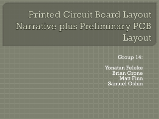
Layout of the OSMOSIS Optical Switch Controller Board using Expedition. or IS hindsight nearly always 20/20 … ?. Outline. OSMOSIS Project Design Entry Board Structure, Materials Signals, Rules, Constraints 1 st Approach 2 nd Approach 3 rd Approach “Final” Approach Conclusion.

E N D
Layout of the OSMOSIS Optical Switch Controller Board using Expedition or IS hindsight nearly always 20/20 … ?
Outline • OSMOSIS Project • Design Entry • Board Structure, Materials • Signals, Rules, Constraints • 1st Approach • 2nd Approach • 3rd Approach • “Final” Approach • Conclusion pdi, Layout of the OSMOSIS OSCB, May 2006
DesignView I/O Designer Design Entry ... HyperLynxPreLayoutSimulations 8 FPGA Designs pdi, Layout of the OSMOSIS OSCB, May 2006
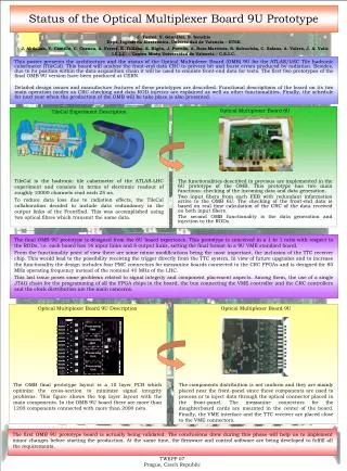
OSCB Chassis Test chassis with a pre-version of the OSCB Board Pre-OSCB OSCI Interface Cards pdi, Layout of the OSMOSIS OSCB, May 2006
OSCB Board Size: 431.8 x 573mm (17" x 22.5")- fits into a 19" chassis 3644 Components 7 FPGAs, 1704 pins 1 FPGA, 1020 pins 40 Slot connectors 20 on front 20 on back each slot connector has 125 pins single ended, 120 diff pin pairs; total of 285 signal pins pdi, Layout of the OSMOSIS OSCB, May 2006
OSCI Conn Connector Fanout Problem Blocked Routing Channels OSCI Conn OSCB Use Blind Vias Free Routing Channels View from Top Half Board Thickness2.0mm minimum (78mils) (16 Layers) 1.8 mm pdi, Layout of the OSMOSIS OSCB, May 2006
1704 pin FPGA (Xilinx FF1704 Package) 12 Rows of signal pins min 12 internal layers(outer layers not used) • ≥ 16 signal layers pdi, Layout of the OSMOSIS OSCB, May 2006
High speed design requirements • 12954 Nets • 4072 diff pairs (clocks + data) • 5000 single ended • Clock frequency: 125MHz, 156MHz • I/O Technology used: - LVPECL Master Clock- LVDS Data, Clk, Sync- LVCMOS Control, uncritical signals • Impedances:- LVPECL 100 Ω balanced- LVDS 100 Ω balanced- LVCMOS 60..70 Ω single ended • Long Wires: up to 750mm (30") pdi, Layout of the OSMOSIS OSCB, May 2006
GND +2.5V GND +1.5V GND GND GND +3.3V GND Board Structure 16s16p Blind Via 1-16, Drill: 0.2mm (8mil)Aspect Ratio 1:11 Blind Via 1-16 Thru Via Thru Via, Drill: 0.45mm (18mil) Aspect Ratio 1:10 S1,H S2,V B.C. Plane, (high εr) S3,H S4,V B.C. Plane, (high εr) S5,H Half Board Thickness ~2.3mm (90mils) S6,V S7,H Danger! S8,V ExcessiveMaterial "LoFlow" Prepreg pdi, Layout of the OSMOSIS OSCB, May 2006
Board Material Isola IS620 • Low Dielectric Loss: <0.01 @ 2..10GHz (FR4: 0.02) • Low Permitivity: εr = 3.5 @ 1GHz (FR4: 4.4) • Low vertical CTE: 40ppm/ºC (FR4: 175ppm/ºC)Lower risk of torn vias! • Cost: ~3x FR4 (“moderate”) • FR4 compatible, but process parameter tuning required pdi, Layout of the OSMOSIS OSCB, May 2006
Rules / Constraints • Done in CES:- 86 Signal Classes- 1 additional Scheme for BGA Areas- 7 Clearance Rules for Netclasses • General Rules Trackwidth (60..70 Ω):Track Width outer: 200 μm (8 mils), inner: 150 μm (6 mils) • Track-to-Track outer: 200 μm (8 mils), inner: 100 μm (4 mils) • Diff Pairs on inner Layers (100 Ω):100-140-100, 100-115-100 (μm) pdi, Layout of the OSMOSIS OSCB, May 2006
Wiring challenge Exception:Local diff pair wiring Each star consists of ~900 Signals pdi, Layout of the OSMOSIS OSCB, May 2006
Challenges • Board Manufacturing:- Size alone not a problem, but...- 100μm Structures alone not a problem, but…- 32 Layers alone not a problem, but…- IS620 alone not a problem, but… All together, - can that be done at all? • Wiring:- 12900 Signals is much, but… 4000 Diff Pairs is incredibly much! but… most of these pairs wired in global stars • This is going to be tough! pdi, Layout of the OSMOSIS OSCB, May 2006
1st Approach PlacementTop: all major comps Bottom: "Chickenfood" "Standard" routingmethod:- PWR/GND- Critical Signals- Top Bottom pdi, Layout of the OSMOSIS OSCB, May 2006
1st Approach - Observations (1) - 6 week effort Only 80% completion (still 1500 opens!) Almost impossible to do test runs - Autorouter takes looong (days!) - manual completion not feasible need breakthrough! pdi, Layout of the OSMOSIS OSCB, May 2006
1st Approach - Observations (2) Autorouter cannot convert blind vias into thru vias: poor FPGA fanout Manually add thru vias under the inner 4 rows of signal pins 8 outer rows 12 rows 4 inner rows Power SupplyThru Via Thru Via (1 btw) Blind Via (1-16)(2 between) Blind Via (1-16)(2 between) pdi, Layout of the OSMOSIS OSCB, May 2006
1st Approach - Observations (3) Autorouter cannot connect a diff pair to different vias blind vias thru vias Diff Pairs Manually convert blind vias to thru vias, where necessary "Workaround":Use route obstructs to guide router Autorouter does not know fences (hard or soft) pdi, Layout of the OSMOSIS OSCB, May 2006
1st Approach - Observations (4) Question of an expert: Why are all FPGAs on the same side? Discussion with manufacturer: FPGAs on both sides can be done place 4 FPGAs on top side and 4 FPGAs on bottom side pdi, Layout of the OSMOSIS OSCB, May 2006
2nd Approach • New FPGA placement – 4 on top, 4 on bottom • Rewire from scratch - except master CLK and supply (0v2, 10sep05) pdi, Layout of the OSMOSIS OSCB, May 2006
2nd Approach - Observations (1) Much better results! (still ~1000 opens) Did not solve the problem,Need breakthrough! Asked Mike Bare from Mentor Graphics: Are we doing something wrong? No principal mistakes, approach seems to be OK. settings seem to be OK. Asked US top PCB „Guru“: Can this board be done? Feasible; forget autorouter! Would do it manually, would need only 12 layers, would take 3 months – too late! MG Switzerland runs an autorouter test without diff pair definition (all signals single ended) 99.8%Completion! 15 opens finished manually in under 1 hour pdi, Layout of the OSMOSIS OSCB, May 2006
2nd Approach - Observations (3) Congestion in the top connector area:Wide single ended bus causes partial blockage of diff pairs Conclusion: Turn top daughtercard slots 180º pdi, Layout of the OSMOSIS OSCB, May 2006
2nd Approach - Observations (4) On the edge of despair… Expedition very, very slow - e.g. „Save“ takes about 10 minutes - e.g. move and drop a simple component (e.g. Cap) can take 10-15 seconds - 2GB of memory not sufficient crashes - Routing passes can take several days - CES seems to extremely slow down Expedition pdi, Layout of the OSMOSIS OSCB, May 2006
3rd Approach • Turn top daughtercard section 180º • Buy new PC - Athlon 64 X2 Dual Core 4800+ - 4GB Memory - Latest MB technology • Rewire from scratch (except power supplies) pdi, Layout of the OSMOSIS OSCB, May 2006
3rd Approach - Observations (1) Further improvement ???? opens Still not the final solution,Need breakthrough!!! Difficult / often impossible to place a diff pair of vias, even if there is enough space No immediate solution, Manually place 2 diff vias individually! No immediate solution, Manual routing! Mostly easy! Measure: Use 4 more layers Too many open diff pairs after autoroute: Router seems to have real difficulties with diff pair fanout out of the BGAs Even with new PC: Slow performance still almost unbearable Use ExtremePCB and ExtremeAR! pdi, Layout of the OSMOSIS OSCB, May 2006
4th Approach – Add 4 more layers (possible without changing board thickness) 16s16p 20s16p S1,H S1,H S2,V S2,V S3,H S3,H S4,V S4,V S5,H S5,H S6,V S6,V S7,H S7,H S8,V S9,H S8,V S10,V pdi, Layout of the OSMOSIS OSCB, May 2006
4th Approach • Use 4 more layers • Install XtremePCB,setup server + 2 client sessions, andAdd one more person • Install XtremeAR setup server + 3 client processes • Remove CESCES slows down Expedition even more with the new pre-release required for running XtremeAR • Rewire from scratch pdi, Layout of the OSMOSIS OSCB, May 2006
4th Approach – Use LDIR Vertical layers are more utilized,especially 5 inner PFGAs need more vertical routing space pdi, Layout of the OSMOSIS OSCB, May 2006
4th Approach – Routing Method (1) - All PWR / GND - Flow Control Bus (single ended) - Master Clock (DP) and Sync Signals (SE), tuning, manual clean-up - Diff Pairs: Partial route (per FPGA) 1) route opposite side - force thru vias 2) route FPGA side - force blind vias 3) route both sides 4) manual Clean-Up pdi, Layout of the OSMOSIS OSCB, May 2006
4th Approach – Routing Method (2) - Repeat Partial Routing / Clean-up... - Single Ended Signals - Tuning - DRC - Clean-Up - DRC - Generate Data pdi, Layout of the OSMOSIS OSCB, May 2006
Supply all done pdi, Layout of the OSMOSIS OSCB, May 2006
Flow Control Bus pdi, Layout of the OSMOSIS OSCB, May 2006
Flow Control Bus pdi, Layout of the OSMOSIS OSCB, May 2006
Flow Control Bus • Global Sync Signals pdi, Layout of the OSMOSIS OSCB, May 2006
Flow Control Bus • Global Sync Signals pdi, Layout of the OSMOSIS OSCB, May 2006
Flow Control Bus • Global Sync Signals • Master Clock (Diff Pairs) pdi, Layout of the OSMOSIS OSCB, May 2006
Flow ControlBus • Global Sync Signals • Master Clock (Diff Pairs) pdi, Layout of the OSMOSIS OSCB, May 2006
Flow Control Bus • Global Sync Signals • Master Clock (Diff Pairs) • Local Diff Pairs (1) pdi, Layout of the OSMOSIS OSCB, May 2006
Flow Control Bus • Global Sync Signals • Master Clock (Diff Pairs) • Local Diff Pairs (1) pdi, Layout of the OSMOSIS OSCB, May 2006
Flow Control Bus • Global Sync Signals • Master Clock (Diff Pairs) • Local Diff Pairs (1) • Local Diff Pairs (2) pdi, Layout of the OSMOSIS OSCB, May 2006
Flow Control Bus • Global Sync Signals • Master Clock (Diff Pairs) • Local Diff Pairs (1) • Local Diff Pairs (2) pdi, Layout of the OSMOSIS OSCB, May 2006
Flow Control Bus • Global Sync Signals • Master Clock (Diff Pairs) • Local Diff Pairs (1) • Local Diff Pairs (2) • Global Diff Pairs (1) pdi, Layout of the OSMOSIS OSCB, May 2006
Flow Control Bus • Global Sync Signals • Master Clock (Diff Pairs) • Local Diff Pairs (1) • Local Diff Pairs (2) • Global Diff Pairs (1) pdi, Layout of the OSMOSIS OSCB, May 2006
Flow Control Bus • Global Sync Signals • Master Clock (Diff Pairs) • Local Diff Pairs (1) • Local Diff Pairs (2) • Global Diff Pairs (1) • Global Diff Pairs (2) pdi, Layout of the OSMOSIS OSCB, May 2006
Flow Control Bus • Global Sync Signals • Master Clock (Diff Pairs) • Local Diff Pairs (1) • Local Diff Pairs (2) • Global Diff Pairs (1) • Global Diff Pairs (2) pdi, Layout of the OSMOSIS OSCB, May 2006
Flow Control Bus • Global Sync Signals • Master Clock (Diff Pairs) • Local Diff Pairs (1) • Local Diff Pairs (2) • Global Diff Pairs (1) • Global Diff Pairs (2) • Global Diff Pairs (3) pdi, Layout of the OSMOSIS OSCB, May 2006
Flow Control Bus • Global Sync Signals • Master Clock (Diff Pairs) • Local Diff Pairs (1) • Local Diff Pairs (2) • Global Diff Pairs (1) • Global Diff Pairs (2) • Global Diff Pairs (3) pdi, Layout of the OSMOSIS OSCB, May 2006
Flow Control Bus • Global Sync Signals • Master Clock (Diff Pairs) • Local Diff Pairs (1) • Local Diff Pairs (2) • Global Diff Pairs (1) • Global Diff Pairs (2) • Global Diff Pairs (3) • Global Diff Pairs (4) pdi, Layout of the OSMOSIS OSCB, May 2006
Flow Control Bus • Global Sync Signals • Master Clock (Diff Pairs) • Local Diff Pairs (1) • Local Diff Pairs (2) • Global Diff Pairs (1) • Global Diff Pairs (2) • Global Diff Pairs (3) • Global Diff Pairs (4) pdi, Layout of the OSMOSIS OSCB, May 2006
Flow Control Bus • Global Sync Signals • Master Clock (Diff Pairs) • Local Diff Pairs (1) • Local Diff Pairs (2) • Global Diff Pairs (1) • Global Diff Pairs (2) • Global Diff Pairs (3) • Global Diff Pairs (4) • Global Diff Pairs (5) pdi, Layout of the OSMOSIS OSCB, May 2006
Flow Control Bus • Global Sync Signals • Master Clock (Diff Pairs) • Local Diff Pairs (1) • Local Diff Pairs (2) • Global Diff Pairs (1) • Global Diff Pairs (2) • Global Diff Pairs (3) • Global Diff Pairs (4) • Global Diff Pairs (5) pdi, Layout of the OSMOSIS OSCB, May 2006