STP Part II
STP Part II. PVST (Per Vlan Spannin g Tree): A Vlan field is added to the BPDU header along with Priority & Mac. Priority is 32768, Mac Address is MAC or that Switch & Vlan is the Vlan number used. That is the reason default priority on Cisco switches is 32769 due to default Vlan 1.

STP Part II
E N D
Presentation Transcript
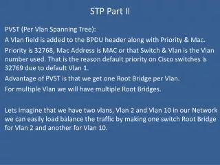
STP Part II PVST (Per Vlan Spanning Tree): A Vlan field is added to the BPDU header along with Priority & Mac. Priority is 32768, Mac Address is MAC or that Switch & Vlan is the Vlan number used. That is the reason default priority on Cisco switches is 32769 due to default Vlan 1. Advantage of PVST is that we get one Root Bridge per Vlan. For multiple Vlan we will have multiple Root Bridges. Lets imagine that we have two vlans, Vlan 2 and Vlan 10 in our Network we can easily load balance the traffic by making one switch Root Bridge for Vlan 2 and another for Vlan 10.
STP Part II The command to Setup a specific switch as Root Bridge for PVST: First Check the commands to verify: Switch(config)# show spanning-tree Check for Root ID and Bridge ID Root ID is info about the Root Bridge Bridge ID is the info about the switch itself. Now make switch as a Root Bridge. (PVST) Switch(config)# spanning-tree vlan 1 root primary Now Switch(config)# show spanning-tree Vlan 1 will become Root Bridge
ETHER CHANNEL ETHERCHANNEL: It is kind of Ether bonding. It is basically adding different ports to 1 logical link for a high bandwidth. It is also used for Load balancing. Also provides failover. Protocols: 1. Port Aggregation Protocol (PAGP): Cisco proprietary It has Auto, Desirable & on port modes. Auto: waits for other link to become ether channel and if acknowledged will become one too. Desirable: doesn’t wait and tell other links to become Ether channel. IF both sides set to Auto no ether channel will be established. On: makes ether channel on but should be manually enabled on both sides.
ETHER CHANNEL 2. Link Aggregation Control Protocol (LACP) It is Industry Standard (802.3AD) It has passive , active & on port modes. Passive: Just like auto in before slide Active: Just like desirable On: Just like on Ether channel comes in two types: Layer 2 and Layer 3 Only difference is that layer 3 bind ports become port-channel (logical layer 3 interface) and we can assign it an IP address.
ETHER CHANNEL CONFIGURATION: Lets port 3 and 4 or switch A connected with port 3 and 4 or switch B respectively and we need to create an Ether channel between them. On Switch A we will use desirable and on Switch B we will use auto. LAYER 2: SwitchA(config)# int range fa 0/3 - 4 SwitchA(config-if-range)# channel-protocol pagp Note: to use “on” mode we need to turn off pagp because on is not a protocol negotiator. SwitchA(config-if-range)# channel-group 5 mode desirable
ETHER CHANNEL LAYER 2: SwitchB(config)# int range fa 0/3 - 4 SwitchB(config-if-range)# channel-protocol pagp Note: to use “on” mode we need to turn off pagp because on is not a protocol negotiator. SwitchB(config-if-range)# channel-group 5 mode auto COMMANDS TO VERIFY: Switch(config)# show ipintbr (Will show port-channel at end) Switch(config)# show etherchannel detail
ETHER CHANNEL LAYER 3: SwitchA(config)# intrange fa 0/3 - 4 SwitchA(config-if-range)# no channel-group 5 SwitchA(config-if-range)# exit SwitchA(config)# int port-channel 1 SwitchA(config)# no switchport [ This command will turnoff layer 2 capabilities of switch port and makes it layer 3 interface] SwitchA(config-if)# ip 192.168.5.10 255.255.255.0 SwitchA(config-if)# exit SwitchA(config)# int range fa 0/3 -4 SwitchA(config-if-range)# no switchport SwitchA(config-if-range)# channel-group 5 mode desirable
ETHER CHANNEL Things to remember: • All ports must use same speed and duplex. • Interface in a bundle are redundant. • Interfaces bundle must be in same vlan / trunk • Interface in bundle cannot be span ports • Change to port-channel affects all ports in bundle • Change to an individual port only affects that specific port. Thank you , Hyp3ri0n www.itpings.com www.linuxworld.co