Download
1 / 32
320 likes | 449 Views
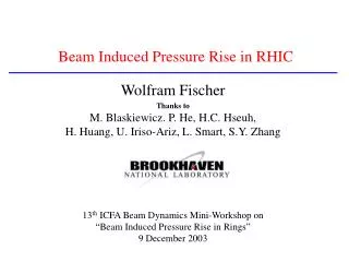
The 13 th ICFA Beam Dynamics Mini-Workshop Beam Induced Pressure Rise in Rings. RHIC electron cloud and vacuum pressure rise characteristics. P.He, H.C.Hseuh, W.Fischer, U.Iriso, D.Gassner, J.Gullotta, R.Lee, L.Smart, D.Trbojevic, L.F.Wang and S.Y.Zhang. Outline.

E N D
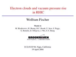
The 13th ICFA Beam Dynamics Mini-Workshop Beam Induced Pressure Rise in Rings RHIC electron cloud and vacuum pressure rise characteristics P.He, H.C.Hseuh, W.Fischer, U.Iriso, D.Gassner, J.Gullotta, R.Lee, L.Smart, D.Trbojevic, L.F.Wang and S.Y.Zhang
Outline Part I: Residual gas composition during RHIC pressure rise Part II: Solenoid field effect on RHIC e-cloud
Accelerator Complex G12 G10 G2 G8 G4 G6
Two type of pressure rises observed at RHIC 2003 run *the beam transition pressure rise for ions *the electron cloud induced pressure rise at the injection The residual gas composition during multipacting and its evolution along the pressure rise is very helpful toward our understanding in this critical issue
H2 CO H2O 1 min Gas Composition and its Evolution along the Pressure Rise(G2)-Beam Transition Pressure Rise
More Concern about Gas Composition and its Evolution along the Electron Cloud induced pressure rise at the injection We will focus on that!
5 mins S.Y.Zhang Gas Composition and its Evolution along the Pressure Rise(G2)
Beam Intensity CCG: 1e-10 to 1e-7 torr H2 CO H2O 10 mins Gas Composition and its Evolution along the Pressure Rise(G12)
Beam Intensity CCG: 1e-9 to 3e-7 torr H2 10 mins CO H2O Gas Composition and its Evolution along the Pressure Rise(G4)
Beam Intensity CCG: 3e-11 to 1e-8 torr H2 10 mins CO H2O Gas Composition and its Evolution along the Pressure Rise(G8)
H2 Residual Gas Spectrum, during multipacting (CERN) CO 30 mins CO2 Different scale respect to the above figure, where peak 2(H2) and 28 have been omitted, to show the behaviour of the peak 18(H2O) H2O
Extensive studies at CERN have shown that water vapour plays an important role in the contribution of the SEY. It is possible that the presence of water molecules increases the sticking probability for other gases. N.Hilleret In-Situ SEY Measurement (CERN)
RHIC Installed 11 x 5.2m x 12cmΦ TiZrV coated pipes this summer coated by SAES Getters with license from CERN at Q3-Q4 with high P during d-Au runs yo1, bo2, yi2(2), bi9(2), yi10(4), ip12 TiZrV NEG coating pipes
H2 CH4 CO A. Rossi NEG still pumping
H2 CO CH4 A. Rossi Evidence of NEG saturation
CC Gauge G12-PWX G12-PW1 G11-PW1 G11-PWX H2 RGA CO Run 2004: one NEG pipe at G11
Beam Intensity G11-PWX G11-PW1 G12-PWX G12-PW1 Comparison with Run 2003: no NEG pipe at G11
H2 RGA Enlarge this area CO CCG Beam Intensity RGA CCG Run 2004: four NEG pipes at YI10
Beam Intensity RGA CCG Run 2004: two NEG pipes at YI2
Part I: Residual gas composition during RHIC pressure risePart II: Solenoid field effect on RHIC e-cloud
Noise level Ubaldo Electron Energy Spectrum
Beam Intensity Beam Intensity ED CCG CCG Solenoid L.Smart Solenoid Field Effect(1)-May 30
SLAC-PUB-9813 Cyclotron Resonance Condition M.Pivi Cyclotron Resonance at RHIC? Cyclotron frequency does not match bunch spacing -further study needed
B can help to fully suppress the e-cloud during fill #3530. (N=1.1 •1010 p-pb). B - Sweep during fill #3812. (N=1.5 •1010 p-pb). Even at the maximum value of B, VED is only reduced by a factor of ~3 (not enough to fully suppress the cloud). ~in RHIC we have ~7% solenoids covering, Maybe more solenoid needed in the future. Solenoid Field Effect(3)
PSR: R.Macek EC was reduced by a factor ~50 by ~20G solenoid field. However, there was no measurable effect on the instability threshold when weak solenoids covering ~10% of the ring circumference were excited.
KEK PF: Y. Suetsugu
Uniform Solenoid Field (Equal Polarity) Y. Suetsugu Non-uniform Solenoid Field (Opposite Polarity)
From the simulation, we can see no electron in the center of the beam pipe if we use equal polarity solenoid field Solenoid Field Effect(4) Run 2004, RHIC solenoid in equal polarity
• Evidence that solenoid will help to reduce the electron cloud build up • Residual gas spectrum show electron stimulated desorption due to multipacting • Improve electron detector design • Verify experimentally the effectiveness TiZrV NEG coating to reduce the electron cloud build up after activated at 250°C(max ~ 1.1) and also after saturation (max <1.2~1.3) • More solenoid(~30%), more NEG pipes(~300m), in-situ SEY measurement Conclusions and Future Works