Download
1 / 7
70 likes | 160 Views
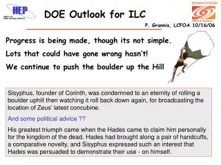
Risk minimum approach for ILC e+ source. Masao KURIKI Hiroshima/KEK. Consider E+ Source Layout (2). Lengths of the RDR e+ systems in meters Undulator Drift&Dogleg Target+ Capture Pre-accelerator TOTAL

E N D
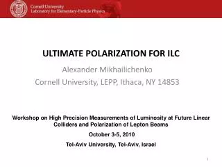
Risk minimum approach for ILC e+ source Masao KURIKI Hiroshima/KEK Global Design Effort
Consider E+ Source Layout (2) • Lengths of the RDR e+ systems in meters Undulator Drift&Dogleg Target+ Capture Pre-accelerator TOTAL 100(200) 400 100 500 1200 V Q?Can we insert a warm 400 MeV E- accelerator in the drift/dogleg section and use the same target/capture, preaccelerator as a new type of “KAS”YES, WHY NOT? Global Design Effort
KASor KAS • We need to review the design requirements for a KAS and its cost/benefits to overall ILC operation. • RDR design has everything (except polarization) at 10% intensity…Injector, L-band linac, tgt/capture section and pre-accelerator. Large and expensive! • An extreme alternate KAS could be a compact S-band single bunch linac whose e- beam uses the photon E+ tgt, capture and pre-accelerator, producing single bunches at a few % intensity. • Inexpensive, compact and could fit between the undulator and target alongside the photon and high energy e beam! Global Design Effort
What is KAS or KAS • 600 MeV driver with 0.4X0 target makes ~3% intensity. • The same driver with 3X0 target makes >20% intensity. • 0.4X0 Ti alloy and 4X0 W has same thickness. Global Design Effort
KAS • Start up e+ source is very important in MD phase. • In the initial phase, 3X0 W-Re instead of 0.4X0 Ti alloy improves the e+ intensity. • 600 MeV single bunch S-band accelerator (30m) can generate >20 % intensity e+ beam. • This single bunch can be accumulated in DR forming the ILC format beam with 20% bunch charge. • This beam is more useful for commissioning. • The target can be replaced when undulator e+ is ready for the commissioning. KAS becomes a small backup with a few % intensity. Global Design Effort
KAS • 400m drift space is enough to accommodate 6 GeV e- linac. • It could be driver linac for conventional e+ source with the full intensity. • It also compatible to Linac based laser compton e+ source. • Tunnel for undulator section is therefore compatible to all schemes which we have considered. Evenafter completion of tunnel, we can switch e+ scheme among them. • Because of this flexibility, this approach (KAS or KAS) minimizes unexpected risks. Global Design Effort
Summary • Risk minimum approach without additional CFS inspired by Ewan’s talk, is considered. • KAS ability can be enhanced by replacing target material at MD phase, when the start up e+ source is more important. • All e+ schemes are compatible to the baseline CFS. • We should consider scenario to minimize possible and unexpected risks. It is an issue in TDP and this approach is one candidate. Global Design Effort