Download
1 / 1
10 likes | 132 Views
Development of an instrumented wheel to assess wheelchair propulsion techniques, measuring resultant force applied to the pushrim. Goals include cost-effectiveness, universal compatibility, and wireless capability. Results demonstrate sensitivity and reliability in measuring strain and force. Future work involves improvements for accuracy and location tracking of applied forces. Detailed methods and circuit design enhancements are discussed.

E N D
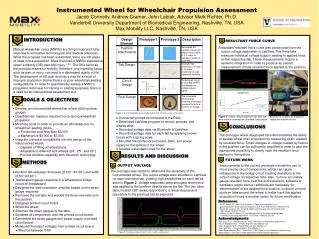
Instrumented Wheel for Wheelchair Propulsion Assessment Jacob Connelly, Andrew Cramer, John Labiak, Advisor Mark Richter, Ph.D. Vanderbilt University Department of Biomedical Engineering, Nashville, TN, USA Max Mobility LLC, Nashville, TN, USA INTRODUCTION Design Element Prototype 1 Prototype 2 Description RESULTANT FORCE CURVE A standard resultant force curve was constructed from the output voltage data taken in LabView. The three tabs measure individual voltage outputs relating to applied force at that respective tab. These measurements require a systemic integration in order to produce an overall measurement of total resultant force applied to the pushrim. Pushrim Attachments Decreased the number of push-rim attachments from 6 to 3 in order to decrease rigidity of push-rim. Manual wheelchair users (MWUs) are living longer and fuller lives due to innovative technological and medical advances. While the progress has been substantial, there are still areas of need in this population. More than half of MWUs experience upper extremity (UE) pain and injury 1,2,3. The UEs serve as the principle means for mobility, therefore, any impeding factor, such as pain or injury, can lead to a decreased quality of life. The development of UE pain and injury may be a result of improper propulsion biomechanics or poor wheelchair seating configurations. In order to quantitatively assess a MWU's propulsion technique for training or seating purposes, there is a need for an instrumented assessment tool. Tab Design Changed tab dimensions in order to increase sensitivity through increased flexibility. Circuit Design Redesigned circuit to increase CMRR and amplify the voltage output signal. Final Design The completed wheel design functions to produce resultant force as a function of voltage. GOALS & OBJECTIVES • Develop an instrumented wheelchair wheel utilizing strain gauges. • Quantitatively measure resultant force during wheelchair propulsion. • Minimize costs in order to provide an affordable tool for wheelchair seating clinics. • Production cost less than $2,000 • Market price $3,000 to $5,000 • Integrate universal compatibility into the design of the instrumented wheel. • Capable of fitting all wheelchairs. • Adaptable to different size wheels (24'', 25'', and 26''). • Provide wireless capability with Bluetooth technology. Figure 1. The initial prototype design changed significantly during the course of the project. Figure 3. Output voltage readings from each tab were used to construct the Standard Curve above. Each tab is routed to its respective bridge and amplifier circuit. • Connected printed circuit board to the DAQ. • Developed LabView program to record, process, and display data. • Recorded voltage data via Bluetooth in LabView. • Recorded voltage data for each tab by applying known forces with a spring scale. • Mounted the printed circuit board, DAQ, and power supply to the spokes of the wheel. • Created a standard curve for the wheel. CONCLUSIONS The prototype wheel developed here demonstrates the ability to assess wheel chair propulsion by measuring strain created by resultant force. Small changes in voltage created by flexion in the pushrim can be sufficiently amplified in order to gain the appropriate sensitivity to clearly track the resultant force applied to the system. RESULTS AND DISCUSSION FUTURE WORK . METHODS OUTPUT VOLTAGE Improvements to the current prototype include the use of more precise circuit components, which can cause imbalances in the bridge circuit creating deviations in the output voltage of respective tabs. Also, to more accurately gauge resultant force over the entire pushrim, software or hardware (angle sensor) additions are necessary for determination of the applied force location. Inclusion of more pushrim tabs around the wheel to better track the applied propulsion forces is another option for future modification. The prototype was tested to determine the sensitivity of the instrumented wheel. The output voltage was recorded in LabView for each individual tab, yielding high sensitivities for each tab as seen in Figure 2. Voltage responses were strongest when force was applied to the pushrim directly above the tab. The two other tabs, located 120° away, responded to a lesser degree and oppositely to the previous tab as expected. • Pushrim tab redesign: thickness (0.125’’0.09’’) and width (0.50’’0.40’’). • Tested strain gauge response in a Wheatstone bridge circuit on breadboard. • Designed the instrumentation amplifier based on the strain gauge response. • Removed the old tabs and welded the three new tabs onto the pushrim. • Designed printed circuit board. • Wired the wheel. • Attached the strain gauges to the tabs. • Soldered all components onto the printed circuit board. • Connected the strain gauges and power supply to printed circuit board. • Measured theoutput voltages from printed circuit board. • Must be between 0-5V. References 1 Sie IH, Waters RL, Adkins RH, Gellman H. Upper extremity pain in the postrehabilitation spinal cord injured patient. Arch Phys Med Rehabil. 1992;73:44–48. 2 Dalyan M, Cardenas DD, Gerard B. Upper extremity pain after spinal cord injury. Spinal Cord. 1999;37:191–95. 3 Gellman H, Sie IH, Waters RL. Late complications of the weight-bearing upper extremity in the paraplegic patient. Clin Orthop. 1988;233:132–35. Acknowledgments Paul King, Ph D. – Faculty Advisor, VUSE Department of Biomedical Engineering Russel Rodriguez M.E. – Project Engineer, Max Mobility LLC Adam Karpinsky M.E. – Project Engineer, Max Mobility LLC Guo Liyon M.E. – Project Engineer, Max Mobility LLC Franz Baudenbacher, Ph D.– Consultant, VUSE Department of Biomedical Engineering Tobias Meyer – Consultant, VUSE Department of Biomedical Engineering Figure 2. The output voltage for tabs 1 (red), 2 (white), and 3 (green). T C