Download
1 / 6
60 likes | 154 Views
Testing conditions and prototype evaluation conducted using a CAEN Module 2527 via long cables. Analysis of noise distribution, crosstalk, and calibration errors in linear and DC-DC channels. Measurement setup for output noise analysis and FFT performed to identify noise components. Results and comparisons between different operating conditions and channel configurations.

E N D
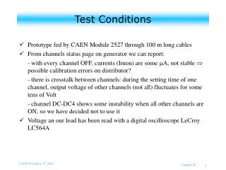
Test Conditions • Prototype fed by CAEN Module 2527 through 100 m long cables • From channels status page on generator we can report: - with every channel OFF, currents (Imon) are someA,not stable possible calibration errors on distributor? - there is crosstalk between channels: during the setting time of one channel, output voltage of other channels (not all) fluctuates for some tens of Volt - channel DC-DC4 shows some instability when all other channels are ON, so we have decided not to use it • Voltage an our load has been read with a digital oscilloscope LeCroy LC564A Vandelli W.
Measurement scopes and method • We’d like to measure prototype output noise distribution: in particular pick-up noise for linear channels and switching noise for DC-DC channels • For being able to use our oscilloscope (max voltage input 400 V peak), a voltage divider, with total resistance 4.4 M and attenuation 15.8, has been used as load for prototype’s HV channel in examination • In order to measure noise distribution FFT has been performed on data directly on the oscilloscope • For being able to discriminate pick-up noise on load and the real noise of prototype we have taken some measurement with load not connected on distributor • Noise has been tested as a function of voltage setting, one channel ON or all channels ON (to check crosstalk and stability) Vandelli W.
LIN6 We seek for noise components in linear channels from 0 to about 10 MHz, with all other channels OFF. Most important contributions come from pick-up and flicker noise. Figure shows in green the signal in time domain and in purple in frequency domain (FFT) Vandelli W.
DC-DC0 Noise distribution in DC-DC channels has been verified from 0 to about 10 MHz, with all other channels OFF. Most important contribution is at 125 kHz; we think that it is the converter switching frequency. This component seems to depend on the voltage setting of the channel: for DC-DC0 at 2 kV it is only 26.5 mV. Pick-up and Flicker noise are at the same level of linear channels. Vandelli W.
We have looked for differences in noise between two opposite conditions: one channel ON and all channels ON. DC-DC6 with all ch. ON DC-DC channel presents a meaningful increase of noise at 125 kHz when it works with all other unload channels (linear and DC-DC) at 4 kV. Vandelli W.
LIN6 with all ch. ON Linear channel shows a small increase of pick-up noise at 50 Hz when it works with all other unload linear channels at 4 kV; but, if we set ON also DC-DC channels, LIN6 channel picks up very large noise at 125 kHz. Vandelli W.