RP1
RP1. 20072. MSD I. 1kg Motor Module, First Generation P08208 – Mechanical Design P08205 – Wireless & PWM Motor Controller. WHAT IS A MOTOR MODULE ?. aka “ MM”. MODULAR MOUNTING. STEER. DRIVE. 100kg. 10kg. 1kg. OFF THE SHELF MOTOR MODULES. RP100 ( Wired ). RP10 ( Wired ). RP1.

RP1
E N D
Presentation Transcript
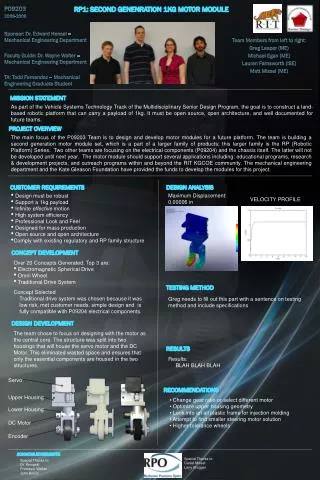
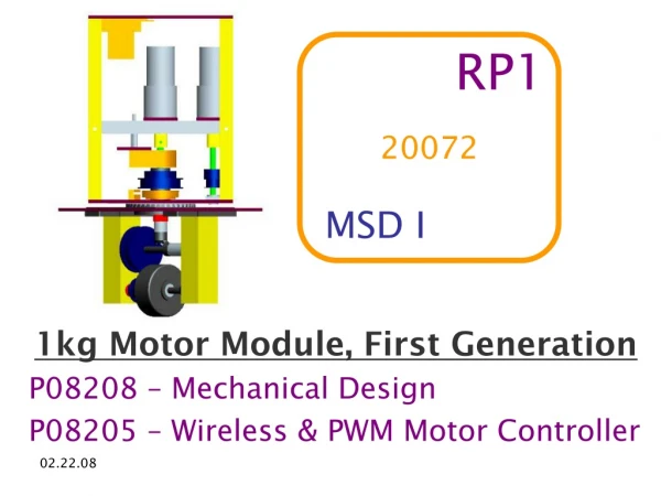
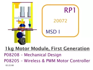
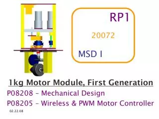
RP1 20072 MSD I 1kg Motor Module, First Generation P08208 – Mechanical Design P08205 – Wireless & PWM Motor Controller
WHAT IS A MOTOR MODULE ? aka “MM” MODULAR MOUNTING STEER DRIVE
100kg 10kg 1kg OFF THE SHELF MOTOR MODULES
RP100( Wired ) RP10( Wired ) RP1 RP10Redesign Sister projects!
Autonomous! RP10Redesign Smaller! Lighter! Wireless! RP1 Robust!
Drive Andrew Anderson Matthew Benedict Platform Eric Rodems Artur Ponikiewski Yoke James Edick Eric Rodems P08205 Reid Williamson Electronics Bryan Jimenez Jonathan Maglaty P08208 Wendy Fung Steer Matthew Benedict Artur Ponikiewski Controls Brendan Hayes Philip Edwards ORGANIZATION BREAKDOWN
System-Level Process Flow Motor Controller Computer Wireless Receiver RP1 Motor Module Microprocessor
CRITICAL REQUIREMENTS • Transport 1kg Payload • Robust = Withstand Tabletop Drop • Wireless Communication • Power Motors with a PWM Signal • Open Source & Open Architecture • Reflect Design of the RP Family • Modular Design for Multiple End Uses
Quantity 2, Fully Functional Size 12in x 6in x 6in Speed @ max efficiency 38 in/s Droptest Repair Time < 5 min Wireless Range 300 ft max Battery Life 1 hour + EXPECTATIONS 2 1
FORMAT Drive & Steering • Q & A Yoke & Platform • Q & A Electronics & Controls • Q & A DFMA & MSD II Outlook • Q & A
DRIVETRAIN SYSTEM • Responsibilities: • Highly dynamic range of operating speeds • An array of different operating conditions • Robustness • Seamless system integration • Risks • Difficulty obtaining different motor gearboxes • Drive Shaft Alignment (turntable wobble) • Robustness of design • Accurateness of systems modeling • Tolerances • Assembly
FINAL DESIGN IG 32 Motor 27:1 Gear Reduction Axle Couplings ¼” Stainless Steel Axles Thrust Bearings ½” Aluminum Spacers 2:1 Synchronous Belt and Pulley 2” Diameter Wheel Axle Collars
STEERING • Responsibilities: • Infinite Steering • Easy to assemble/disassemble • Robust • Seamless system integration • Risks • Robustness of belt tension system • Turntable • Integration with electronics and controls • Tolerances • Assembly
STEERING SUBSYSTEM IG 32 Motor 71:1 Gear Reduction ¼” Stainless Steel Axles 1:3 Synchronous Belt and Pulleys Custom Centerpost Turntable
STEER BELT TENSION Adjustable Steer Motor Mounting Plate Axle Couplings Adjustable Bearing Plate
DRIVE & STEERING Q & A
YOKE • Responsibilities: • Responsible for structural skeleton of Rp1 • Design a rigid and robust framework • House all other sub-systems within framing • Provide protection against a 36” drop to the floor • Risks • Keeping within the weight requirements • Withstand drop without any significant damage or misalignment of components • Minimizing overall cost of yoke
UPPER YOKE 1/8” AL Plate ½” x ½” Al Posts AL Angle Brackets 1/8” Al Motor Mounting Plates Encoder standoff mounting plate 1/8” Al Upper Yoke to Turntable Mounting Plate
LOWER YOKE 1/8” Al Upper Yoke to Turntable Mounting Plate 80/20 90° Base Connector 1”x1” AL 80/20 Quick Frame Mounted Flanged sleeve bearings
Design Justification • Critical Decisions: • Frame built of aluminum instead of Lexan to improve strength • Used an open 80/20 fork design for lower yoke to provide maximum rigidity while minimizing weight • Used solid post box design in upper yoke to fully enclose drive, steering and electrical systems. Solid posts allows for easier hardware attachment • Turn table connected to mounting plates on both sides to support upper and lower yoke
PLATFORM Responsibilities Platform design Mounting of modules to platform Idler module development Test fixture design Risks Design was heavily reliant on upper yoke Design of platform for drivability
DRIVE PLATFORM 2 platforms (1 per team) • Holds 2 motor modules • Holds 2 idler modules • Square shape for adaptability
IDLER MODULE Idler Design Past RP project experience Use of motor module parts Simplified design Caster offset (slot)
TEST PLATFORM 1 test platform • Holds 1 motor module • Holds 2 idler modules • Will have quick connect adapters spec’d out from Molex
YOKE & PLATFORM Q & A
CONTROLS • Graphical User Interface (GUI) • Allow the user to interact with and control the robotic platform • Wireless • Responsible for the communication between the user and the platform • Microprocessor • Generate control signals and monitor sensor feedback
Controls • Risks • GUI • User is unaware of current state of RP1 • User is unable to respond quickly • Wireless • Wireless interference • Insufficient data rate • Microprocessor • “Swamped” with encoder feedback
GUI • Final Design Wheel Angle Battery Life Remaining Left Motor Module Drive Motor: Good Right Motor Module Drive Motor: Inefficiency Left Motor Module Steering Motor: Good Right Motor Module Steering Motor: Good
MIB520 USB-Gateway MICAz 2.4 GHz Wireless Transceiver Wireless
Microprocessor • Freescale MC9S12DT256 • 8 Channel PWM Module • Modular Communication • IIC • SPI • SCI • CAN
ELECTRONICS • System Responsibilities • Provide components for motor control • Placement of motor control components • Supply power to electrical components • Confirm electrical components are compatible with microprocessor • Risks • Component ratings (i.e. heat, amps, etc.) • Lead time on final part selections • Compatibility between electrical components
H-bridge PWM Motor Controller 3A Encoders US Digital EM5 EM1 HUBDISK Final Design
Power Schematic for encoders (5V) Final Design
Final Design • Simulation for Encoder Power Schematic
Final Design • Battery Selection • NiMH • 24V • 3.5Ah • Rechargeable
CONTROLS & ELECTRONICS Q & A
Design For Manf. & Assembly • Steering assembly implementation • Degree of machining precision • Bending of motor shaft • Spacing and fasteners • Control Communication • Functional control
Build RP1 prototype Test accuracy of system modeling Build test fixture Do the drop test Look into possible aesthetical improvements Optimize current design Build GUI Setup basic wireless communication Test all electrical components Full system integration and test Plans for MSD II