Mapping from E-R Model to Relational Model
Mapping from E-R Model to Relational Model. Yong Choi School of Business CSUB. Objectives of logical design. Translate the conceptual design into a logical database design that can be implemented on a chosen DBMS later Input: conceptual model (ERD)

Mapping from E-R Model to Relational Model
E N D
Presentation Transcript
Mapping from E-R Model to Relational Model Yong Choi School of Business CSUB
Objectives of logical design... • Translate the conceptual design into a logical database design that can be implemented on a chosen DBMS later • Input: conceptual model (ERD) • Output: relational schema, normalized relations • Resulting database must meet user needs for: • Optimal data sharing • Ease of access • Flexibility
Why do I need to know this? • CASE tools can perform many of the transformation steps automatically, but.. • Often CASE tools cannot model complexity of data and relationship (Ternary relationships, supertype/subtypes, i.e..) • You must be able to perform a quality check on CASE tool results * Mapping a conceptual model to a relational schema is a straight-forward process…
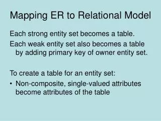
Basics * A conceptual model does not include FK information * • An entity turns into a table. • Each attribute turns into a column in the table. • The identifier of the entity turns into a PK of the table.
Basics (con’t) • There is no such thing as a multi-valued attribute (phone #) in a relational database. • If you have a multi-valued attribute, take the attribute and turn it into a new entity of its own thru the normalization process (see later slide..).
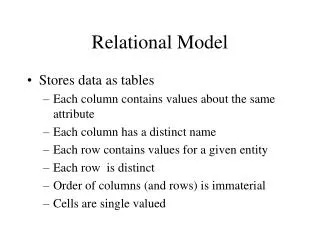
Some rules... * Remember! The Relational DB Model does not like any type of redundancy. • Every table must have a unique name. • Attributes in tables must have unique names. • Every attribute value is atomic. • The order of the columns is irrelevant. • The order of the rows is irrelevant.
The key... • Relational modeling uses primary keys and foreign keys to maintain relationships • Primary keys are typically the unique identifier noted on the conceptual model
The key... (con’t) • Foreign keys are the PK of another entity to which an entity has a relationship • See the class web for “PK as FK” & “Referential integrity” • Composite primary keys are keys that are made of more than one attribute • Weak entities • Associative (Bridge) entities (M:N relationship)
Constraints… • Entity integrity constraints • A PK attribute must not be null. • Referential integrity constraints • matching of primary and foreign keys
Emp_Id Emp_Lname Emp_Fname Salary Mapping an entity into a relation • An Entity name: Employee • Attributes: • Emp_ID, Emp_Lname, Emp_Fname, Salary • Identifier: Emp_ID Employee
Mapping an entity into a relation title year Movies title year length filmType Movies Star Wars 1977 124 color Mighty Ducks 1991 104 color Wayne’s World 1992 95 color length filmType
Mapping binary relationships • One-to-one: PK on the mandatory side becomes a FK on the optional side • one-to-one mandatory relationship • Restaurant DB: BillingAddress and Customer • One-to-many: PK on the one side becomes a FK on the many side • Many-to-many - create a new relation (bridge entity) with the PKs of the two entities as its composite PK
Mapping a 1:1 relationship • Nurse: • Nurse_ID, Name, Date_of_Birth • Care Center • Center_Name, Location, Date_Assigned
Mapping a 1:1 relationship FK: Nurse_ID
Mapping a 1:M relationship • Customer: • Customer_ID, Customer_Name, Customer_Address • Order: • Order_ID, Order_Date
Mapping an M:N relationship Warehouse A component of composite PK is a FK of other relations StockInfo Product
Mapping composite and Multi-valued attributes to relations • Composite attributes: use only their simple, component attributes – divide into atomic and separate attribute. • Multi-valued attributes: become a separate relation with a FK taken from the superior entity.
Mapping composite attributes to relations Composite attribute
SSN Name Phone# Mapping a multi-valued attribute Employee Employee (SSN, Name) Phone (SSN, Phone#)
Mapping a weak entity • Becomes a separate relation with a FK taken from the superior entity • Primary key composed of: • Partial identifier of weak entity • Primary key of identifying relation
Mapping a weak entity Employee NOTE:The FK of DEPENDENT should NOT allow null value if DEPENDENT is a weak entity Dependent
Mapping 1:M recursive (or unary) relationships Employee FK • Manager_ID references Emp_ID
Mapping M:N recursive (or unary) relationships • In manufacturing assembly line, several items consist of multiple items as components. • One item can be used to create other items. • Associations among items are M:N. • the associations among items are M:N. That is, there is a M:N unary relationship.
Mapping M:N recursive (or unary) relationships Has_components (a) Bill-of-materials relationships (M:N) Used_by (b) ITEM and COMPONENT relations
Mapping Supertype/subtype relationships • Create a separate relation for the supertype and each of the subtypes • Assign common attributes to supertype • Assign PK and unique attributes to each subtype • Assign an attribute of the supertype to act as subtype discriminator
Mapping Supertype/subtype relationships Sub symbol