Download
1 / 179
1.84k likes | 2.24k Views
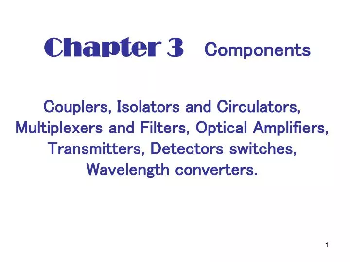
Chapter 3 Components. Couplers, Isolators and Circulators, Multiplexers and Filters, Optical Amplifiers, Transmitters, Detectors switches, Wavelength converters. 3.1 Couplers [ wavelength independent, wavelength selective for 1.31/1.55 multiplexing]. 1. α. 1-α. α : coupling ratio

E N D
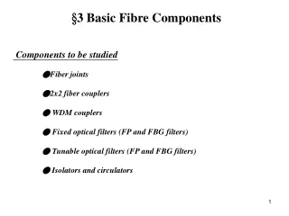
Chapter 3 Components Couplers, Isolators and Circulators, Multiplexers and Filters, Optical Amplifiers, Transmitters, Detectors switches, Wavelength converters.
3.1 Couplers[wavelength independent, wavelength selective for 1.31/1.55 multiplexing] 1 α 1-α α:coupling ratio 3dB couple α= 1/2 α= 0.95 (for monitoring)
For multiplexing 1310nm 1310nm 1550nm 1550nm For EDFA 1550nm 1550nm 980nm or 1480nm 980nm or 1480nm Def: excess loss: the loss of the device above the fundamental loss introduced by the coupling ratio α Example: A 3dB coupler may have 0.2dB excess loss
a1→ → b1 → b2 a2→ 3.1.1 Principle of Operation E: electrical field S-parameters For lossless couplers
Similarly the sum of output power is proportional to If it is lossless This relation holds for arbitrary Eq(3.4) can be extended to any number of ports
3.2 Isolators and Circulators (nonreciprocal devices) Isolators are for transmitter, circulators are for add and drop or others. The insertion loss should be small ~ 1dB A circulator is similar to an isolator except it has multiple ports.
SOP= state of Polarization 3.2.1 Principle of Operation of an Isolator
A spatial walk-off polarized splits the signal into two orthogonally polarized components.
3.3 Multiplexer and Filters Multiplexers and filters are for WDM, add/drop. WXC,
passband skirt The desired characteristics of filters • Low insertion loss • Polarization-independent loss • Low temperature coefficient • Reasonable broad passbands • Sharp passband skirts • Low cost a. integrated-optic (may be polarization dependent) b. all-fiber devices
F-P 3.3.1 Gratings Any device whose operation involves interference among multiple optical signals originating from the same source but with different relative phase shifts. An exception is a device where the multiple optical signals are generated by repeated traversals of a single cavity (etalons).
Principle of Operation The pitch of the grating (distance between adjacent slits)=a Assuming plane wave is incident at angle : diffraction angle The slits are small compared to λ, phase changes across a slit is negligible
For construction interference at λ occurs at the image plane if
The energy at a single λ is distributed over all the discrete angles that satisfy (3.9). For WDM only light of a certain order m will be collected, the remaining energy is lost. m=0 has most energy θi= θd The wavelengths are not separated. blazed reflection grating maximize the light energy at α
( 3.3.2 Diffraction Pattern Relax the constrain a <<λ, the phase change across the slit is not negligible, consider a slit of length from The relative phase shift of the diffracted light from y at an angle θ compared to that from y=0 is given by
The amplitude A(θ) at θ (Ref: Optics, page401) Fourier Transform of rectangular slit. For any diffracting aperture f(y)
3.3.3 Bragg Gratings (BGs) BGs are widely used in WDM BGs: any periodic perturbation in the propagating medium. (periodic variation of n) (Fiber BGs are written by UV) BGs can also be formed by acoustic waves.
Principle of Operation Consider two waves with β0 and β1 propagating in opposite directions. If the Bragg phase-matching condition is satisfied when Λ= the period of the grating Consider β1 wave propagating from left to right, Then the energy from this wave is coupled onto a scattered wave traveling from right to left at the same wavelength provided.
These reflections add in phase, when the path length in λ0 each period is equal to half the incident wavelength λ0
Δλ: detuning from λ0 Δ is inversely proportional to the length of the grating Apodized grating: the refractive index change is made small toward the edges of the grating => increasing the main lobe width The index distribution over the length of BG is analogous to the grating aperture in sect3.3.2. The side lobes arise due to the abrupt start and end of the grating, which result in a sinc(.) behavior for the side lobes. Apodization is similar to pulse shaping to reduce the side lobes of signal spectrum.
3.3.4 Fiber Gratings (FGs) • Useful for filter, add/drop compensating dispersion • Advantages: a. low loss (0.1dB) b. ease of coupling c. polarization insensitivity d. low temperature coefficient e. simple packaging f. extremely low cost • Made from photosensitive fiber (Ge-doped) UV intensity ↑ n↑] change of n ~ 10-4 • Two kind of FGs a. short period (Bragg Grating Λ~ 0.5μm) b. long period (Λ~ 100+μm – 1000+μm)
Fiber Bragg Gratings (FBG) • extremely low loss ~ 0.1dB • high wavelength accuracy (±0.05nm) • high crosstalk suppression (Fig 3.8) (40dB) • flat tops • typical temperature coefficient ~1.25x10⁻²nm/℃ For passive temperature-compensated ~ 0.07x10⁻²nm/℃
Long-Period Fiber Grating (a few intermeters) Useful for EDFA gain (equalization) They may be cascaded to obtain the desired profile.
Principle of Operation The propagating mode in core couples onto the modes in the cladding => induce loss For a given λ coupling occurs depending on Λ β= propagation constant of the core mode : propagation constant of the path order cladding mode The phase matching condition
cladding core Let and be the refractive indices of the core and the path-order cladding modes
3.3.5 Fabry-Perot Filters This filter is called Fabry-Perot interferometer or etalon. Principle of Operation The wavelengths for which the cavity length is an integral multiple of half the wavelength in the cavity are called resonant wavelengths.
A round trip through the cavity is an integral multiple of the wavelength. • The light waves add in phase. Assume r1=r2 t1=t2 The reflectance R=r1r2 A: absorption loss of mirror T=t1t2=transmission
A=0, R=0.75, 0.9 and 0.99 TFP (f) is periodic function with period FSR Where FSR: free spectral range = The spectral range between two successive passband = 1/2τ
is the smallest value satisfied the condition
Tunability 1. change cavity length 2. change refractive index n Recall The wave with frequency will be selected. • mechanical tuning • piezoelectric tuning => thermal instability, hysteresis
3.3.6 Multilayer Dielectric Thin-Film Filters A thin-film resonant multicavity filter (TFMF) consist of two or more cavitied. Advantages: flat top, sharp skirt, low loss, insensitive to the polarization
3.3.7 Mach-Zehnder Interferometers (MZI) Usage: filter, MUX/DEMUX, modulator, switch Problems: • wavelength drift caused by aging or temperature variation • not exact 50:50 • not flat top passbands Change temperature (or refractive index) of one arm=> tuning
through low arm 由第一個3dB coupler 產生delayπ/2 through upper arm 由第二個coupler 到第二個output 產生delayπ/2 所以互相cancel At the upper output . The signal all through the upper arm as reference. The signal through the lower arm and the upper output has phase lag At the lower output the phase difference
consider K MZI interconnected The path length difference for the kth MZI is assumed to be