Download
1 / 16
160 likes | 178 Views
This summary covers the operation and upgrades of superconducting cavities for the Super-KEKB accelerator. Highlights include increased max current to 1270mA, power boost to 380kW, and HOM power at 14kW. Voltage ranges from 1.4MV to 2.0MV. The average trip rate is once per month for good vacuum conditions. Upgrades involve optimizing input couplers, HOM dampers, and integrating new technologies for higher power operation. Testing of new crab cavities and damper systems are also planned.

E N D
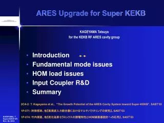
Superconducting Cavities for Super-KEKB S. Mitsunobu
Summary of KEKB SCC Operation • Max. Current1270mA • Max. Power for Beam 380kW • HOM Power14kW • Operation Voltage 1.4-2.0 MV • Average Trip rate is once per month for good vacuum condition. .
KEKB SC Super-KEKB SC • Cavity Field 1.4-2.0MV OK • Input Coupler 380kw 460kW OK(500kW) • Input Coupler Qext 7x10⁴ 5x10⁴ • HOM Power 10 kW 60kW (test 43 kW) • Large Gate Valve D=220mm to be solved • Add 4 Cavities • Larger Sigma z should be studied
Dedicated 1 MW klystron system for coupler test bench Testing high power coupler, at D10 area new 1MW klystron power supply and klystron system have been constructed. One of limitation of high power operation for KEKB coupler is heating at capacitor for bias voltage. An air duct is added near this capacitor to increase cooling power. Couplers could operate more than 500 kW.
Cap of Doorknob Air Duct
HOM Damper • Cooling limit (4.0m/sec ) 60kW • Inner Surface Temperature Limit 200 ℃ • KEKB 80kw with 4A at 3mm BL(2.5pC) • D=220 mm Beam Pipe 56 kW(4A,3mm) • KWKB could be operate (4A, 4MM, 1.8pC) P=k(σz)・I**2/frev/Nb
A SBP HOM damper have been tested up to 18 kW and 25 kW for LBP HOM damper.
Crab cavity • Crab cavities will be install in KEKB ring next winter shutdown. • New crab cavity design for SKEKB have been proposed by Akai.
New crab cavity (Coaxial type) • (Left) The cross-shaped waveguide dampers and coaxial dampers are attached at the squashed-cell. • (Right) Cross section of the coaxial damper at the cut plane of Y-Y’. Proposed by Akai
Summary • KEKB SC will be used with small modification for Super-KEKB. • Coupler already tested more than 500kW(800kW in short time),beam test will be done. • HOM damper is most important issue for Super-KEKB SC. (43kW reached) • Crab cavities going to be test soon.