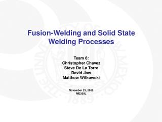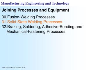
High-Performance Welding Processes: Roll Bonding, Friction Welding, Resistance Welding
Explore roll bonding, friction welding, and resistance welding processes in manufacturing for high-performance applications, understanding key factors affecting welding quality, joint size, and shape. Learn about different test methods and innovative applications.


High-Performance Welding Processes: Roll Bonding, Friction Welding, Resistance Welding
E N D
Presentation Transcript
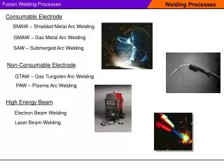
COLD WELDING-pressure is applied to the two parts-At least one of them is ductile-usually performed on non ferrous metals-Interface must be well cleaned
ROLL BONDING-used in manufacturing some US coin- can be performed on cold or hot temperatures-typical example is claddingas shown in following figure
FIGURE 31.1 Schematic illustration of the roll bonding, or cladding, process.
FRICTION WELDING- ONLY ONE PART IS ROTATED-THE OTHER PART IS PRESSED AGAINST THE FIRST PART- A flash is developed by plastic deformation (upsetting)
FIGURE 31.3 Sequence of operations in the friction-welding process: (1) The part on the left is rotated at high speed. (2) The part on the right is brought into contact with the part on the left under an axial force. (3) The axial force is increased, and the part on the left stops rotating; flash begins to form. (4) After a specified upset length or distance is achieved, the weld is completed. The upset length is the distance the two pieces move inward during welding after their initial contact; thus, the total length after welding is less than the sum of the lengths of the two pieces. The flash subsequently can be removed by machining or grinding.
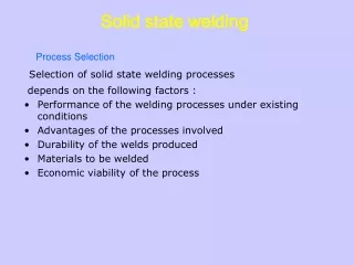
THE SIZE AND SHAPE OF THE WELD JOINT DEPENDS UPON1. Amount of heat generated2. Thermal conductivity of the two materials3. Mechanical properties of the two materials at elevated temperature4. Rotational speed5. Axial pressure applied
FIGURE 31.4 Shape of the fusion zones in friction welding, as a function of the axial force applied and the rotational speed.
RESISTANCE WELDINGHeat required for welding is produced by means of electrical resistance across the two parts to be joined
FIGURE 31.6 (a) Sequence of events in resistance spot welding of a lap joint. (b) Cross-section of a spot weld, showing the weld nugget and the indentation of the electrode on the sheet surfaces. This is one of the most commonly used processes in sheet-metal fabrication and in automotive-body assembly.
FIGURE 31.7 Two electrode designs for easy access to the components to be welded.
FIGURE 31.8 Spot-welded (a) cookware and (b) muffler. (c) A large automated spot-welding machine. The welding tip can move in three principal directions; sheets as large as 2.2 m × 0.55 m (88 in. × 22 in.) can be accommodated in this machine, with proper workpiece supports. (d) A spot welding machine.Source: (c) and (d) Courtesy of Taylor-Winfield Technologies, Inc.
TEST METHODS FOR SPOT WELDING1. Tension-shear test2. Cross-tension test3. Twist test4. Peel test
FIGURE 31.9 Test methods for spot welds: (a) tension-shear test, (b) cross-tension test, (c) twist test, and (d) peel test (see also Fig. 32.9).
FIGURE 31.10 (a) Seam-welding process in which rotating rolls act as electrodes; (b) overlapping spots in a seam weld; (c) roll spot welds; and (d) mash seam welding.
FIGURE 31.11 Two methods of high-frequency continuous butt welding of tubes.
DIFFUSION BONDING- used in joining dissimilar metals- Strength of the joints results from:1. Diffusion: movement of atoms across the interface2. plastic deformation at the interface
FIGURE 31.19 The Monosteel piston. (a) Cutaway view of the piston, showing the oil gallery and the friction-welded sections; (b) detail of the friction welds before the external flash is removed and cylindrical grooves are machined. Produced by inertia friction welding