Download
1 / 51

E N D
1. Course OPTO 356 (Physical Optics) Dr. Ashraf OPTO 356 1
2. Course Grades OPTO 356 2
3. Course index OPTO 356 3
4. Lecture 1 Nature of Light
Light is made-up of photons which are very small particles of energy. When these photons move or the light travels, it travels in straight lines but in small waves with a velocity called a speed of light. The speed of light is approximately 300 000 km per second.� An example would be tossing a pebble into a pond. The ripples produced, (small waves) travel in a straight line away from the source, the pebble.� Light shares the characteristics of both particles and waves.
Light is a form of radiant energy that you can detect with your eyes. Light energy comes from chemical energy, electrical energy and nuclear energy. It is a combination of electrical and magnetic energy that travels very, very fast.
The light can pass through anything that is transparent, sort of passes through translucent objects (frosted window) but doesn't make it through opaque objects such as a brick wall.
OPTO 356 4
5. What is light?
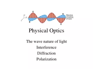
Light is an electromagnetic (EM) wave propagating through space. The EM waves (photons) include:
ultraviolet radiation
visual light
infrared radiation
radio waves, etc.
The Light is a transverse wave. This means that the oscillation is perpendicular to the direction of motion (much like a water wave). So what causes light to exist and move? In physics it is known that a changing magnetic field causes a changing electric field (and visa versa). A photon consists of a time varying electric and magnetic field which regenerate each other! As far as we know this will go on forever unless the photon gets absorbed (by an atom or collection of atoms).
OPTO 356 5
6. OPTO 356 6
7. OPTO 356 7
8. OPTO 356 8
9. OPTO 356 9
10. OPTO 356 10
11. Quantum Energy
Just like particles, photons carry energy. Each wavelength has a unique energy given by the expression below (Einstein again!)
Let "c" be the speed of light (3x10⁸ m/s), then we have
E = h f or h n
E = h C/ l
Where
E = quantum energy
h = Planck's constant = 6.626 X 10 -34
C = Speed of light
= wavelength
f or n = the frequency
Long waves, such as radio waves, carry little energy.
Short waves, like X-rays, carry lots of energy.
This is why ultraviolet radiation can give you a sunburn and cause cancer OPTO 356 11
12. The propagation of light
In the 1700s and before, experiments seemed to indicate that light was composed of particles. In the early 1800s, a physicist Thomas Young showed that light exhibited wave characteristics.
Further experiments by other physicists culminated in James Clerk (pronounced Clark) Maxwell collecting the four fundamental equations that completely describe the behavior of the electromagnetic fields. James Maxwell deduced that light was simply a component of the electromagnetic spectrum. This seems to firmly establish that light is a wave
The advent of quantum physics successfully explained the photoelectric effect in terms of fundamental particles of energy called quanta. Quanta are known as photons when referring to light energy.
The electromagnetic energy of light is a form of electromagnetic radiation.
The electro magnetic theory holds that light is propagated as oscillating transverse fields. The energy is equally divided between the electric field E and the magnetic field B which are mutually perpendicular. The propagation motion will be perpendicular on both field OPTO 356 12
13.
Light and similar forms of radiation are made up of moving electric and magnetic forces. A simple example of motion similar to these radiation waves can be made by dropping a pebble into a pool of water. In this example, the water is not actually being moved by the outward motion of the wave, but rather by the up-and-down motion of the water. The up-and-down motion is transverse, or at right angles, to the outward motion of the waves. This type of wave motion is called transverse-wave motion. The transverse waves spread out in expanding circles until they reach the edge of the pool, in much the same manner as the transverse waves of light spread from the sun. However, the waves in the pool are very slow and clumsy in comparison with light, which travels approximately 186,000 miles per second.
OPTO 356 13
14. Light radiates from its source in all directions until it is absorbed or diverted by some substance (fig. 2-1). The lines drawn from the light source (a light bulb in this instance) to any point on one of the transverse waves indicate the direction that the wavefronts are moving. These lines, are called light rays
OPTO 356 14
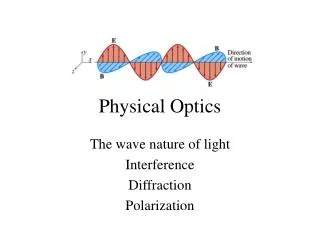
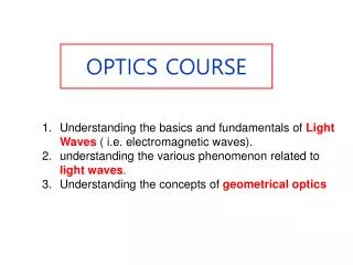
15. Characteristics of light
Three important characteristics
1- Rectilinear propagation:
Light travel in straight line
2- Reflection:
When light incident on a smooth surface it turns back into the original medium
3- Refraction
The path of light changes when it enters a transparent medium OPTO 356 15
16. Properties of Light
When light waves, which travel in straight lines, encounter any substance, they are either reflected, absorbed, transmitted, or refracted. This is illustrated in figure 2-2. Those substances that transmit almost all the light waves falling upon them are said to be transparent. A transparent substance is one through which you can see clearly.
Clear glass is transparent because it transmits light rays without diffusing them (view A of figure 2-3). There is no substance known that is perfectly transparent, but many substances are nearly so. Substances through which some light rays can pass, but through which objects cannot be seen clearly because the rays are diffused, are called translucent (view B of figure 2-3). The frosted glass of a light bulb and a piece of oiled paper are examples of translucent materials. Those substances that are unable to transmit any light rays are called opaque (view C of figure 2-3). Opaque substances either reflect or absorb all the light rays that fall upon them.
Figure 2-2. - Light waves reflected, absorbed, and transmitted. OPTO 356 16
17. OPTO 356 17
18. All substances that are not light sources are visible only because they reflect all or some part of the light reaching them from some luminous source.
Examples of luminous sources include the sun, a gas flame, and an electric light filament, because they are sources of light energy. If light is neither transmitted nor reflected, it is absorbed or taken up by the medium. When light strikes a substance, some absorption and some reflection always take place. No substance completely transmits, reflects, or absorbs all the light rays that reach its surface. OPTO 356 18
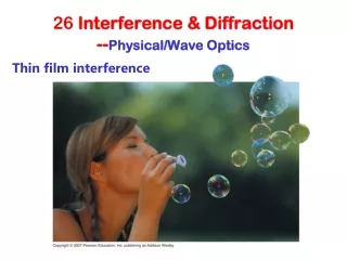
19. What is interference When two waves of identical wavelength are in phase, they form a new wave with an amplitude equal to the sum of their individual amplitudes (constructive interference). When two waves are of completely opposite phase, they either form a new wave of reduced amplitude (partial destructive interference) or cancel each other out (complete destructive interference). Much more complicated constructive and destructive interference patterns emerge when waves with different wavelengths interact.
OPTO 356 19
20. OPTO 356 20
21. Constructive vs. destructive interference
the Waves that combine Constructive in phase add up to relatively = interference
high irradiance. (coherent)
the waves that combine 180�
Out of phase cancel out and yield = Distractive in zero irradiance. Interference
Coherent
Waves that combine with
lots of different phases = incoherent
nearly cancel out and yield
very low irradiance.
Irradiance = power of EM radiation at a surface, per unit area (W m-2) OPTO 356 21
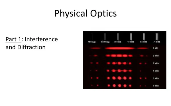
22. Consider a plane wave falling on two slits. The circular wave patterns from the two slits interfere. The key to understanding is to consider the signal that goes in a particular direction. This may fall on a screen far away, or it may be focused by a lens. If d is the separation between the slits and is the angle, then the extra distance traveled by light from one slit (the lower one in this picture) is d sin q. Peaks will occur at angles when the waves are in step:
d sin q= n l for peaks (1)
Where n is an integer (0,1,2,3...). It is called the order of the fringe. n = 0 is the straight-ahead bright fringe.
Zeroes occur at angles when the waves are exactly out of step: the path length differs by half a wavelength (or one and a half, or two and a half).
d sinq = (n +1/2) l for Zeros
For dark area
d sin q= n l/2
for bright area
d sin q= n l
OPTO 356 22
23. OPTO 356 23
24. The past equation can put in measurable quantities using the length of the image from the center of the screen (y) to the distance from the object (slits) to the screen (x) by measuring the angle between them q
Sin q = tan q = y / x
By using this quantities in equation 1 and 2 we get
At Bright fringes : yd / x = n l
Where n = 0,1,2,3,�.
At Dark fringes: yd / x = n l /2
Where n = 1,3,5,7,�. OPTO 356 24
25. Example In young�s experiment. The two slits are 0.04 mm a part, and the screen is located 2 m away from the slits. The third bright fringes from the center is displaced 8.3 cm from the center fringes.
A) Determine the wavelength of the incident light
B) where will the second dark fringes appear?
Solution
For the third fringes n =3 d = 0.04mm x = 2m y = 8.3 cm
yd / x = n l
l =y. d / (n . X)
l =8.3 x 10-2 x 4 x 10-5/ (3 . 2)
l =5.53 x 10⁻⁷ m = 553 nm
b) For the Second dark fringes n = 3 find y
y d / x = n l /2
y =n. l. X / (2d)
y =3 x 5.53 x 10-7 x 2 / (2 x 4 x 10-5)
y = 4.15 x 10⁻² m OPTO 356 25
26. The diffraction grating is working as yang's experiment. It is consist of thousand of lines (slits) in very small area the distance between those slits is the same width. The grating will for the bright and sharper diffraction pattern only. The ray of the diffraction grating is focused on the screen using a lens. The grating is a constrictive interference with first and second till forth order. Each order is less brightens than the higher and so on ( 1st order > 2nd order >3rd >4th )
The condition for formation the bright fringes in the diffraction is the same as young�s experiment. Therefore we can write the grating equation as.
d sin qn = n l
Where n = 1,2,3,4,��.The number of order not the fringes
d = spacing of slits
l = Wavelength of incident light
qn = deviation angle for nth bright fringes
Diffraction Grating OPTO 356 26
27. The first order is occurs when n =1. The image occurs when the path of different rays from each slit differ by an amount equal to one wavelength. The 2nd order image occurs when the path differ by two wavelength
OPTO 356 27
28. Example A diffraction grating having 20.000 lines/in. is illuminated by parallel light of wavelength 589 nm. What are the angle at which the first order and second order bright fringes are formed?
Answer:
The slit spacing d that corresponds to 20,000 lins/in is
d = 2.54 cm/in / 20,000 lines/in = 1.27 x 10⁻⁴cm
The first order bright occurs at n =1 so
sin q1 = n l /d = 5.89 x 10⁻⁵ / 1.27 x10-4 = 0.464
q1 = sin-1(0.464) = 27.6o
The Second order at n =2
sin q2 = 2 x 0.464 = 0.928
q2 = sin -1 (0.928) = 68.1o
The third order will not be formed because sin qn can not exceed 1 because the beam will not deviated by an angle greater than 90o OPTO 356 28
29. Resolving power of instruments To see two objects distinctly, need qobjects � qmin
qobjects is angle between
objects and aperture:
qmin is minimum angular separation
That aperture can resolve:
Where sin qo is called RP (resolving power) OPTO 356 29
30. qo = sin qmin
qo = 1.22 l/D
Where D is the diameter of the objective lens( object)
l is the wavelength
Now by studying the below figure we will notice that
qo = 1.22 l/D = so/p
Where so = the distance between the two object (slits)
p = the distance from the slits to the objective lens
OPTO 356 30
31. To measured the radius of the center maximum in the diffraction pattern we use the focal point of the objective lens.
R = f qo = f so/p
Where f is the focal point
Notice
1- it should be have a distance between the two object to have resolving power
2- the distance between the two object will make an angle q between the interference of the two wave that coming from the two object
3- we have no distance between the two object we get a complete interference that make zero angle so we have no RP OPTO 356 31
32. One of the largest refracting telescope in the world is the 40 in diameter instrument at yerkes Observatory in Wisconsin; its objective lens has a focal length of 19.8m (65ft).
a) What is the minimum separation of two features of the moon�s surface such that they are just resolved by this telescope?
b) What is the radius of the center maximum in the diffraction pattern set up by the objective lens? (For white light, the central wavelength of 500 nm can be used for computing the resolution. The moon is 3.84 x 10⁵ km from the earth
The solution
p = 3.84 x 10⁵ km = 3.84 x 10⁸ m
l = 500 nm = 500 x 10-9 = 5 x 10⁻⁷m
D = 40 in = 40 x 2.54 x 10-2 = 1.02 m OPTO 356 32
33. p = 3.84 x 10⁵ km = 3.84 x 10⁸ m
l = 500 nm = 500 x 10-9 = 5 x 10⁻⁷m
D = 40 in = 40 x 2.54 x 10-2 = 1.02 m
This minimum separation distance so is determine by
qo = 1.22 l / D = so/p
so = 1.22 l p / D
so = 1.22 x 5 x 10-7 x 3.84 x 108/ 1.02
so = 230 m
R = f so/p
R = 19.8 x 230 / 3.84 x 10⁸
R = 1.19 x 10⁻⁵ m
The 200 in reflecting telescope at Mt. Palomar in California can distinguish features on the moon 46.3 m (or 152 ft) apart
OPTO 356 33
34. The polarization Light The light is formed from two propagation wave front
Vertical wave and horizontal wave this is related to the nature of light that have two perpendicular wave ( electric wave and magnetic wave)
Linear light Circular light OPTO 356 34
35. Polarization light:
it is the process by which the transverse oscillations of a wave motion are confined to a definite pattern
If two polarizers are set up in series so that their optical axes are parallel, light passes through both. However, if the axes are set up 90 degrees apart (crossed), the polarized light from the first is extinguished by the second. As the angle rotates from 0 to 90 degrees, the amount of light that is transmitted decreases. This effect is demonstrated in the following diagram. The polarizers are parallel at the top and crossed at the bottom.
Parallel light analyzer
Perpendicular light analyzer
OPTO 356 35
36. OPTO 356 Intensity Distribution of the Interference Pattern 36
37. Interference depends on the relative phase of the two waves.
It also depends on the path difference between them.
The resultant intensity at a point is proportional to the square of the resultant electric field at that point. OPTO 356 37
38. OPTO 356 38
39. Phasor Addition of Waves Consider a sinusoidal wave whose electric field component is given by the expression.
Where Eo is the wave amplitude
w is the angular frequency
Now consider a second sinusoidal wave
whose electric field is given by
The wave have the same amplitude but
have different phase f with respect to the wave E1.
The resultant wave which is the sum of E1
and E2 can be shown by the graph and
in mean time with
OPTO 356 39
40.
Where sin A + sin B = 2 sin [(A+B)/2] cos [(A-B)/2]
So the final total electric field will be
The light intensity of light will be
Since most light detecting instruments measure the time average light intensity and the time average value of over one cycle is � we can write the average intensity as
Where Io is the maximum possible intensity but in your mind that
From the last two equations
We can determine the intensity as OPTO 356 40
41.
Alternatively, since sin q = y /L for small values of q, we can write the intensity equation in the form
Constrictive interference which produce intensity maxima, occurs when the quantity (pyd/lL) is an integral multiple of p, corresponding to y = (lL /d)m
OPTO 356 41
42. Michelson Interferometer The Michelson interferometer produces interference fringes by splitting a beam of monochromatic light so that one beam strikes a fixed mirror and the other a movable mirror. When the reflected beams are brought back together, an interference pattern results. OPTO 356 42
43.
Precise distance measurements can be made with the Michelson interferometer by moving the mirror and counting the interference fringes which move by a reference point. The distance d associated with m fringes is
d = ml /2
OPTO 356 43
44. Laser
The stimulated emission of light is the crucial quantum process necessary for the operation of a laser.
OPTO 356 44
45. Laser Concept OPTO 356 45
46. OPTO 356 46
47. OPTO 356 47
48. OPTO 356 48
49. OPTO 356 49
50. Holography Holography is "lensless photography" in which an image is captured not as an image focused on film, but as an interference pattern at the film. Typically, coherent light from a laser is reflected from an object and combined at the film with light from a reference beam. This recorded interference pattern actually contains much more information that a focused image, and enables the viewer to view a true three-dimensional image which exhibits parallax. That is, the image will change its appearance if you look at it from a different angle, just as if you were looking at a real 3D object. In the case of a transmission hologram, you look through the film and see the three dimensional image suspended in midair at a point which corresponds to the position of the real object which was photographed. OPTO 356 50
51. These three images of the same hologram were taken by positioning the camera at three positions, moving from left to right. Note that the pawn appears on the left side of the king in the left photo, but transitions to the right of the king as you sweep your eye across the hologram. This is real parallax, which tells you that the image is truly 3-dimensional. Each perspective corresponds to looking through the hologram at a particular point. OPTO 356 51
52. Properties of Holography Some of the descriptions of holograms are
"image formation by wavefront reconstruction.."
"lensless photography"
"freezing an image on its way to your eye, and then reconstructing it with a laser"
A consistent characteristic of the images as viewed:
1- The images are true three-dimensional images, showing depth and parallax and continually changing in aspect with the viewing angle.
2- Any part of the hologram contains the whole image!
3- The images are scalable. They can be made with one wavelength and viewed with another, with the possibility of magnification.
OPTO 356 52