Download
1 / 36
360 likes | 511 Views
Impact of Ultra Wide-Band Antennas on Communications in a Spatial Channel. Mohamed El-Hadidy & Thomas Kaiser University of Duisburg-Essen Faculty of Engineering, Department of Communication Systems, Bismarckstr. 81, 47057 Duisburg, Germany Email: el-hadidy@nts.uni-due.de.

E N D
Impact of Ultra Wide-Band Antennas onCommunications in a Spatial Channel Mohamed El-Hadidy & Thomas Kaiser University of Duisburg-Essen Faculty of Engineering, Department of Communication Systems, Bismarckstr. 81, 47057 Duisburg, Germany Email: el-hadidy@nts.uni-due.de
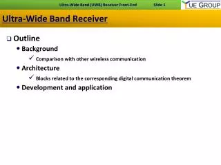
Mathematical frame of UWB system model How the whole chain of the UWB transmisson modeled, including the antennas‘ effects? Omni-directional or Directionl antennas? Impact of antennas on the spatial channel and some simulation results. Future work Outline
Complete UWB Chain Ant_Tx Ant_Rx Channel Tx Rx IEEE Ray Tracing Directional Omni-Directional
Complete UWB Chain Ant_Tx Ant_Rx Channel Tx Rx * *
HFSS Radiation Pattern of Horn Antenna Freq = 6.5 GHz
HFSS Gain in dB from Radiation Pattern Freq = 3 GHz
HFSS Gain in dB from Radiation Pattern Freq = 3.5 GHz
HFSS Gain in dB from Radiation Pattern Freq = 4 GHz
HFSS Gain in dB from Radiation Pattern Freq = 4.5 GHz
HFSS Gain in dB from Radiation Pattern Freq = 5 GHz
HFSS Gain in dB from Radiation Pattern Freq = 5.5 GHz
HFSS Gain in dB from Radiation Pattern Freq = 6 GHz
HFSS Gain in dB from Radiation Pattern Freq = 6.5 GHz
HFSS Gain in dB from Radiation Pattern Freq = 7 GHz
HFSS Gain in dB from Radiation Pattern Freq = 7.5 GHz
HFSS Gain in dB from Radiation Pattern Freq = 8 GHz
HFSS Gain in dB from Radiation Pattern Freq = 8.5 GHz
HFSS Gain in dB from Radiation Pattern Freq = 9 GHz
HFSS Gain in dB from Radiation Pattern Freq = 9.5 GHz
HFSS Gain in dB from Radiation Pattern Freq = 10 GHz
Bowtie Antenna Antenna radiation pattern
Ideal Omni-Directional Directional Rotating Tx & Rx by 90° Rotating Tx by 90° Overall Channel Impulse Response
Future Work • Investigating the diversity added to the UWB MIMO system using the antennas’ impact (e.g. using different types of antennas, rotating the antennas, etc.) • Investigating the coupling effect appearing among the neighbouring antennas either at transmit or receive sides for UWB MIMO system. • Embedding the whole antenna properties which is angular and frequency dependent into the system like polarization and input impedance, etc.