Download
1 / 27
270 likes | 378 Views
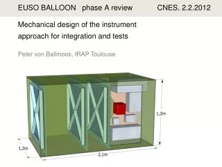
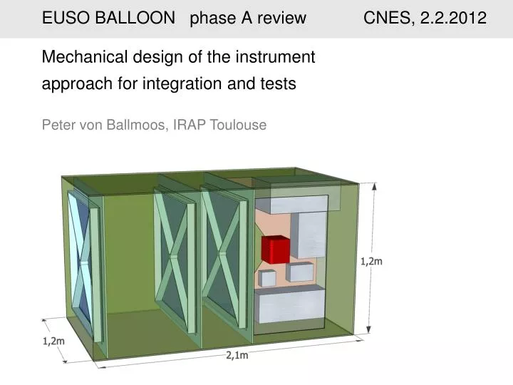
EUSO BALLOON phase A review CNES, 2.2.2012. Mechanical design of the instrument approach for integration and tests Peter von Ballmoos, IRAP Toulouse. EUSO BALLOON instrument overview. data processing. optical system. Photo detection. Payload architecture - conventions.

E N D
EUSO BALLOON phase A review CNES, 2.2.2012 Mechanical design of the instrument approach for integration and tests Peter von Ballmoos, IRAP Toulouse
EUSO BALLOON instrument overview data processing optical system Photo detection
Payload architecture - conventions PDM Platform 3 / lens 3 Platform 2 / lens 2 Platform 1 / lens 1 z x y grooved surfaces
Constraints on the instrument/gondola design optics : "12° (± 6°) of Alex "adopted to 95% by the "optics team" - allowed tolerances vary from 0.2–4 mm (axial) 1-5 mm (lateral) for the 3 lenses. - lens 3 has to be adjustable in z-direction by ± 2 cm - distance between PDM-optics has to be adjustable by ± 2 - precision of distance PDM-optics is ± 1 mm thermal : - lens1 might get expose to temperatures as low as -60°C - PDM and lens 2&3 should remain between 10°C and 20°C (TBC) - need for cooling of the PDM is not to be excluded at this point. - avoid condensation and ice on lenses (particularly lens 3) operations : - "integrity" requirement at the parachute opening 10g/5g - prepare for recovery at sea
Alignment of the lenses and the PDM - tolerances Objective : as representative as possible for JEM-EUSO design with short focal lenght (1.48 m) and fairly large FOV of ± 6° z tolerances TBC ± 4.2mm ± 2.7mm ± 0.2mm 1 x 1 m tilt tolerances TBD ~ 1,48 m ± 0.2mm x,y tolerances TBD
Alignment of the lenses and the PDM Objective : as representative as possible for JEM-EUSO design with short focal lenght (1.48 m) and fairly large FOV of ± 6° ± 1mm ± 1mm ± 20mm (res ± 0.1mm) 1 x 1 m ~ 1,48 m ± 20mm (res ± 0.1mm) 1) Platform 1 and platform 2 are directly fixed within the phone booth 2) Lens 3 shifts in z-direction by ± 20 mm 3) Distance - optics block (lens-1-2-3) is adjustable within ± 20 mm
The mounting and alignment of the Fresnel lenses The mounting of the lenses has to satisfy the following requirements : a) minimize lens sag b) optical alignment compatible with to the tolerances required c) phonebooth must be watertight d) lens thermal expansion/retraction e) stability/simplicity
The mounting and alignment of the Fresnel lenses plug+ (seal) platform (bulkhead) gasket lens spider
The mounting and alignment of the Fresnel lenses a) lens sag : the four arms of a spider shall support the only 8 mm thick PMMA lens to minimize deformation under its own weight. b) alignment : - axial reference (in z-direction) : inward pointing surface of the spider length of the "nose" defines distance to platform - lateral reference (x,y-directions) : "plug" in the center of the spider. platform nose-length lens z-reference plane spider
The mounting and alignment of the Fresnel lenses c) watertight : - seal between lens and platform makes phonebooth watertight. at least lens 1 and 2 – lens 3 is mounted "from above" and might not need to be watertight. d) lens thermal expansion/retraction: - the lens is fixed in its center - only weakly constrained for expansion/retraction within the x-y plane. - pressure provided by the seal allows for minute movements related
integration and tests integration at IRAP Toulouse, clean/balloon hall G. Roudil, IRAP tests of imaging/PSF by use of IRAP collimators/lasers (in case the optics do not go to MSFC) verification of geometry by use of a laser tracker - B. Mot, IRAP
RISKS Failure of mechanical subsystem RI2.1 Fresnel lenses not matched by platform mechanics Spider or Lenses can be re-machined easily RI2.2 Fresnel lens(es) damaged or polluted during integration Lenses will be protected at any time, Protection removed for launch RI3.2 Project exceeds available M/power resource envelope Phase A to define tasks, organization and necessary manpower. Phase A review to assess this point.
A roof-rack for the Bells and Whistles laser IR-camera roof-rack
"stabilized" gondola (LPMA, 2003) The period of the oscillations is typically in the order of 20 s .
motto for scientific ballooning "Success is the ability to go from failure to failure without losing your enthusiasm" Churchill
Payload architecture – thermal aspects fibrelam panels painted white styrofoam ?
http://www.hexcel.com/Resources/DataSheets/Panel-Data-Sheets/Fibrelam_global.pdfhttp://www.hexcel.com/Resources/DataSheets/Panel-Data-Sheets/Fibrelam_global.pdf
Payload architecture – thermal aspects thermal cover inside black outside white
electronics functional block scheme – harness ? from "dossier de definition" Marco Casolino et al. 10/2011