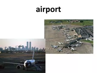
AIRPORT
AIRPORT . LECTURE#05. Typical Runway Lengths. Useful Load = MTOW - OEW. Runway width. ICAO recommends the pavement width varying from 18m to 45m for different types of aircraft.

AIRPORT
E N D
Presentation Transcript
AIRPORT LECTURE#05
Typical Runway Lengths Useful Load = MTOW - OEW
Runway width • ICAO recommends the pavement width varying from 18m to 45m for different types of aircraft. • The width of runway pavement depends upon the transverse distribution of traffic at a distance from the center line of runway pavement. It is found that the aircraft traffic is more concentrated in the central 24m width of the runway pavements. • Another consideration in determining the runway width is that the outer most machine of larger jet aircraft using the airport should not extend off the pavement on to the shoulders. This is because the shoulder is usually of loose soil or established soil etc. which is likely to get into the engine and damage it.
Sight Distance • Generally not an issue in case of runways because longitudinal gradient are quite gentle • Hazardous conditions • Crossing of runways (intersecting runways) • Crossing of taxiway • ICAO Criteria
Longitudinal Gradients on Runways (FAA) • Increase the required length of the runway • Effect aircraft performance • Maximum gradient change 1.5% for groups C, D and E. Use 2% for groups A and B • Vertical curve length (1000 x grade change in feet for groups C, D and E). Use 300 x grade change for groups A and B • Min. distance between points of intersection (1000 ft. for each 1% grade change for groups C, D and E) • Max. 0.8% grade in first quarter of runway (both ends)
Transverse gradient • Transverse gradient is essential for quick drainage of surface water.
Runway sections • Runway shoulders • Runway blast pads • Runway Safety Area (RSA) • Obstacle Free Zone (OFZ) • Object Free Area (OFA) • Runway Protection Zone (RPZ) • Threshold
Runway Shoulders • Runway shoulders provide resistance to blast erosion and accommodate the passage of maintenance and emergency equipment and the occasional passage of an airplane veering from the runway. • A natural surface, e.g., turf, normally reduces the possibility of soil erosion and engine ingestion of foreign objects. Soil with turf not suitable for this purpose requires a stabilized or low cost paved surface.
Blast Pads • A specially prepared surface placed adjacent to the ends of the runways to eliminate the erosive effect on pavement surfaces by high jet engine efflux forces produced by the airplanes at the beginning of their takeoff rolls.
Blast Pads • Also known as overrun areas or stopways, are often constructed just before the start of a runway where jet blast produced by large planes during the takeoff roll could otherwise erode the ground and eventually damage the runway. • Overrun areas are also constructed at the end of runways as emergency space to slowly stop planes that overrun the runway on a landing gone wrong, or to slowly stop a plane on a rejected takeoff or a take-off gone wrong. • Blast pads are often not as strong as the main paved surface of the runway and are marked with yellow chevrons. Planes are not allowed to taxi, take-off or land on blast pads, except in an emergency.
Runway Safety Area (RSA) • A runway safety area (RSA) or runway end safety area (RESA) is defined as "the surface surrounding the runway prepared or suitable for reducing the risk of damage to airplanes in the event of an undershoot, overshoot, or excursion from the runway.” • Past standards called for the RSA to extend only 60m (200 feet) from the ends of the runway. Currently the international standard ICAO requires a 90m (300 feet) RESA starting from the end of the runway strip (which itself is 60m from the end of the runway), and recommends but not requires a 240m RESA beyond that.
Runway Safety Area (RSA) • In the U.S., the recommended RSA may extend to 500 feet in width, and 1,000 feet beyond each runway end (according to FAA recommendations; 1000 feet is equivalent to the international ICAO-RESA of 240m plus 60m strip). The standard dimensions have increased over time to accommodate larger and faster aircraft, and to improve safety.
Obstacle Free Zone (OFZ) • The Obstacle Free Zone (OFZ) is a three dimensional volume of airspace below 150 feet (46 m), above the established airport elevation which protects for the transition of aircraft to and from the runway. • It is centered above the runway and the extended runway centerline and is intended to provide clearance protection for aircraft landing or taking off from the runway and for missed approaches.
Obstacle Free Zone (OFZ) • The runway OFZ extends 200 feet beyond each end of the runway. The width is as follows: 1) For runways serving large airplanes, the greater of: a) 400 feet, or b) 180 feet, plus the wingspan of the most demanding airplane plus 20 feet per 1,000 feet of airport elevation. 2) For runways serving only small airplanes: a) 300 feet for precision instrument runways. b) 260 feet for other runways serving small airplanes with approach speeds of 50 knots or more. c) 120 feet for other runways serving small airplanes with approach speeds of less than 50 knots.
Object Free Area (OFA) • A two-dimensional ground area centered on a runway, taxiway, or taxi lane centerline which is clear of objects, except for objects that need to be located in the Object Free Area for air navigation or aircraft ground-maneuvering purposes.
PLAN Runway Object Free Area (ROFA) & Runway Safety Area (RSA)
Section A-A Runway Object Free Area (ROFA) & Runway Safety Area (RSA)
Runway Protection Zone (RPZ) • “An area off the runway end to enhance the protection of people and property on the ground” in the event an aircraft lands or crashes beyond the runway end.. (FAA) • The Runway Protection Zone, or RPZ, is a trapezoidal shaped area which has specific land use limitations in order to keep the approach to an airport runway clear of obstacles. It is comprised of the Object Free Area, the Extended Object Free Area, and the Controlled Activity Areas.
Runway Protection Zone (RPZ) • Two components of RPZ • The central portion and • The controlled activity area • The central portion of the RPZ extends from the beginning to the end of the RPZ, centered on the runway centerline. Its width is equal to the width of the runway OFA. • The RPZ dimension for a particular runway end is a function of the type of aircraft and approach visibility minimum associated with that runway end.
Threshold • The beginning of that portion of the runway available for landing. • When the threshold is located at a point other than at the beginning of the pavement and the portion of pavement behind the threshold may be used for takeoffs in either direction and landings from the opposite direction, it is referred to as a displaced threshold.
Taxiway • Taxiway provides access to the aircrafts from the runways to the loading apron or service hanger andback • Permits safe, fluent and expeditious movement of aircraft • Load bearing strength of taxiway should be greater than or equal to that of runway
Taxiway Taxiway Runway Typical configuration of Runway and Taxiway
Taxiway • Two parallel taxiways on which aircraft can taxi in opposite directions are termed as “Dual parallel taxiways”. • “Apron taxiway” is located on the periphery of an apron to provide un interrupting taxing of aircraft across the apron. • A “Taxi lane” is provided in aircraft parking area and is used for access between the taxiways and the aircraft parking position.
Taxiway • “Exit taxiways” are provided at suitable locations along the length of runway to clear the runway off the landed aircraft. • The design of taxiway system is governed by • the volume of aircraft movement, • the runway configuration and • the location of the terminal building and other ground facilities.
Factors to be considered for layout of taxiway • Taxiway should be so arranged that the aircrafts which have just landed and taxiing towards the apron, do not interfere with the aircrafts taxiing for take-off. • At the busy airport, taxiway should be located at various points along the runway so that the landing aircraft leaves the runway as early as possible and keeps it clear for use by other aircrafts. Such taxiway are called exit taxiway.
Factors to be considered for layout of taxiway • The route for taxiway should be so selected that it provides the shortest practicable distance from the apron. • As for as possible, the intersection of taxiway and runway should be avoided. • Exit taxiway should be designed for high turn off speeds. This will reduce the runway occupancy time of aircraft and thus increase the airport capacity.
Strength of taxiway The strength of a taxiway should be at least equal to that of the runway it serves, due consideration being given to the fact that a taxiway will be subjected to a greater density of traffic and , as a result of slow moving and stationary aero planes, to higher stresses than the runway it serves.
Geometric Design Standards For Taxiway • Length • Width • Gradients • Width of safety area • Sight distance • Turning radius • Fillets • Separation Clearance Requirements
Geometric Design Standards For Taxiway • Length– should be as short as practicable. • Width – lower than the runway width. This is because the aircraft run on the taxiway are not airborne and the speed of the aircraft on taxiway is lower. Hence pilot can easily maneuver the aircraft over a smaller width of taxiway. • Width of safety area – it includes width of taxiway pavement plus shoulder on either side.
Taxiway Geometrics (ICAO) Max. 4% Max. 3.33% *If the taxiway is intended to be used by airplanes with an outer main gear of wheel span of less than 9 m. ** If the taxiway is intended to be used by airplanes with an outer main gear of wheel span equal to or greater than 9m.
Taxiway Safety Area The surface alongside the taxiway prepared or suitable for reducing the risk of damage to an airplane unintentionally departing the taxiway.
Sight distance • Less distance compared to RW, since the speed is slower on the TW. • Recommendation - Where a change in slope on a taxiway cannot be avoided, the change should be such that, from any point: • 3 m above the taxiway, it will be possible to see the whole surface of the taxiway for a distance of at least 300 m from that point, where the code letter is C, D or E; • 2 m above the taxiway, it will be possible to see the whole surface of the taxiway for a distance of at least 200 m from that point, where the code letter is B; and • 1.5 m above the taxiway, it will be possible to see the whole surface of the taxiway for a distance of at least 150 m from that point, where the code letter is A.
Taxiway curves • Any change in the direction of a taxiway is to be accomplished by the use of a curve whose radius is determined by the taxiway design speed. • Transitional curves are normally not required except for rapid exit taxiways.
Taxiway curves Typical minimum radii for various speeds
Turning radius • Whenever there is change in direction of a taxiway, a horizontal curve is provided. • The curve is so designed that the aircraft can negotiate it without significantly reducing the speed. Circular curve with larger radius is suitable for this purpose. • The radius is given by R = V2/127f. • where; R is radius in m, • V is speed in kmph and f is 0.13. • Subsonic jet transport – min. 120m. • Supersonic jet transport – min. 180m.
Fillets • Taxiway width is increased at horizontal curves by providing fillets. • The inside edge of a taxiway on a curve is termed as fillet. • Design parameters • R = Radius of taxiway turn • F = Fillet radius • L = Length of lead into fillet • W = width of taxiway
Fillets • Widened taxiway on curves • Minimum radii of fillets are dependent on angle of intersection and wheel base of turning aircraft Fillet Radii (in meters)