Download
1 / 56
560 likes | 716 Views
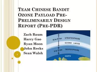
Team Chinese Bandit Ozone Payload Critical Design Report (CDR ). Zach Baum Harry Gao Ryan Moon Sean Walsh. Table of Contents. Mission Goal Objectives Requirements Electrical Design Software Design Thermal Design Mechanical Design Payload Construction Plan Mission Operations

E N D
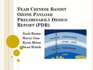
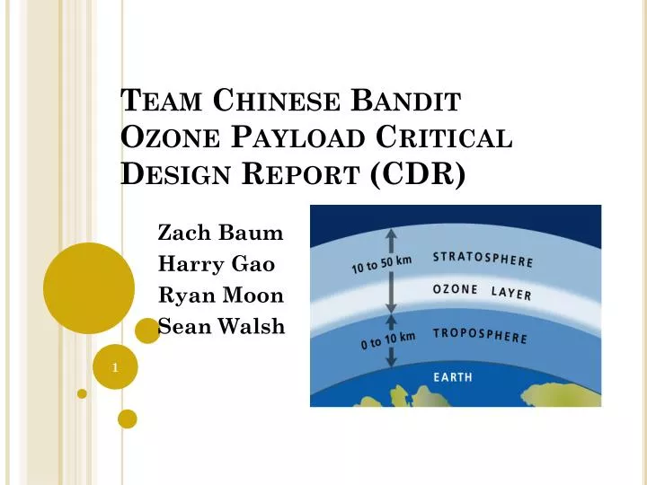
Team Chinese BanditOzone Payload Critical Design Report (CDR) Zach Baum Harry Gao Ryan Moon Sean Walsh
Table of Contents • Mission Goal • Objectives • Requirements • Electrical Design • Software Design • Thermal Design • Mechanical Design • Payload Construction Plan • Mission Operations • Master Schedule • Master Budget
MISSION GOAL • Create a profile of ozone concentration with respect to altitude from ground level to 100,000ft. Ozone sensor reading for 2012 UND/UNF HASP payload
Science Objectives • Map peak of ozone concentration in upper atmosphere. • Create ozone concentration profile with respect to altitude. • Map out any fluctuations within ozone profile.
Technical Objectives • The payload must measure ozone concentration • The onboard program will be able to: • Take temperature readings within close proximity to ozone sensor • Maintain proper operating temperature for all necessary components
Science Requirements • The payload must take measurements of ozone concentration every 3 seconds • Team Chinese Bandits must receive time and altitude GPS information for analysis from LaACES management • The payload must measure the peak ozone concentration to within .2ppmv
Technical Requirements • The payload must: • Not have a mass greater than 500g • Not exceed 3oz/in2 on any surface • Have two holes 17in apart through which the payload will interface with the balloon • Costs must remain within the allotted $500 budget for Chinese Bandits • In order for the payload to create an ozone profile of the atmosphere, the following requirements must be met: • Payload must take measurements of ozone concentration throughout the flight • Payload must be recovered for post-flight analysis • Altitude must be known to within 65 feet • For the accuracy to be known within 65 feet, the following requirements must be met: • Real-time clock must be synced with GPS time during pre-flight • Real-time clock must be accurate to within 3 seconds of the LaACES LASSEN iQGPS
SensorsOzone Sensors • ITO acts as a variable resistor whose resistance changes in the presence of ozone • Applying a constant current allows us to relate the change in output voltage to the resistance and ozone concentration as measured by each sensor • Has a small operating temperature range, therefore a thermal controlling system will be needed
SensorsOzone Sensors • Calibration data will be obtained from Dr. Patel • The equation can be used to relate the resistance of each sensor to the ozone concentration • Y = sensor resistance, X = concentration of ozone, m = slope of the calibration curve, b= y-intercept of curve
SensorsThermistor • KC003T-ND thermistor
Heater • KHLV-101/5 Kapton Heater • 1in. X 1in. • Provides up to 5W of heat with 28V max voltage
Ozone Sensor Interfacing • Zero temp-coefficient circuit for the constant current source
Thermistor Interface • Different constant current, op amp
Power Supply and Distribution • Two power sources: one 9V, one 12V
Heater and Relay Configuration • Will Use a 2N3904 transistor as a relay • BASICStamp will send 3V to base pin to saturate it, allowing the 12V load to flow through the transistor and power heater • 10KΩ resistor placed before the base pin will limit the base current that can flow into the transistor
Payload Construction PlanHardware Fabrication and Testing • Full system testing will be conducted after each subsystem is tested and proven • Payload design will be updates after testing • A delay in any subsystem will cause combined testing to be delayed
Integration Plan • After each subsystem is tested, individual systems will be connected together to ensure interfaces work properly • Electrical/software interfacing has been tested and proven • Tests on interfacing electrical, mechanical, and thermal will ensure proper operation temperature can be maintained • Testing will be done on all systems in a simulated flight to complete payload integration
Flight Software Implementation and Verification • Flight software was tested with electrical prototypes to ensure it was functioning correctly • Pre-Flight will be loaded the day before flight to clear EEPROM and sync GPS time to RTC • A computer located on site will be used to run programs and retrieve data
Flight Certification Testing • Tests will be conducted to ensure payload can survive flight • Temperatures of -70°C to 30°C • Pressure of .163mBar to 1000mBar • Impact upon landing • A shock test and a thermal/vacuum test will be conducted
System Testing Procedure • Payload needs to survive 8.94 m/s • H = 4.08m or 13.38 ft. • Procedure checklist • Power up payload • Run preflight software • Run flight software • Drop from13.4 feet onto the floor • Run post-flight software • Verify that all onboard electronics are operating properly
Vacuum Test Procedures • Power up payload • Run preflight software • Run flight software • Place payload in Vacuum Testing Chamber • Make sure that vacuum chamber is sealed and pressure gauge is turned on • Simulate flight environment in vacuum testing chamber. • This include having a temperature range -70 to 30C • This include pressure of .163 mBar- 1000 mBar • Run post-flight software • Analyze and verify data
System Testing Results ITO removed from box • Preliminary tests done to test if sensors will work • Spark gap created in box to create ozone • ITO warmed to operating temperature and placed in box until 480 seconds ITO placed in box • After speaking with Dr. Patel, long reaction times may be due to not enough ozone to fully react, or not enough airflow across the sensor
Pre-Launch Requirements and Operations:Calibrations • Two Instruments that require calibration • Thermistor • Calibrate for low temperature of 20°C • Calibrate for high temperature range of 35°C • ITO Sensor • Do not have necessary equipment to calibrate • Will be provided by Dr. Patel of the University of North Florida
Pre-Launch Requirements and Operations:Calibration Procedures • Thermistor • Fill glass with cold water in a heat metal container • Place thermometer and thermistor • Record the sensor reading using the voltmeter and flight software for temperature from 20°C to 35°C • ITO • Will be provided by Dr. Patel ITO Circuit Thermistor Circuit
Flight Requirements, Operations and Recovery • Batteries will provide the BalloonSat and sensors with enough power for the duration of the flight • EEProm will have enough memory to take measurements for the duration of the flight • Must find and recover EEProm during recovery; Extra BallonSats will be brought in order to retrieve the data from the EEProm
Data Acquisition and Analysis Plan: Ground Software • The following procedure will be used to complete Ground Software and export flight data.
Data Acquisition and Analysis Plan:Data Analysis Plan • ADC values will be converted into ozone measurements in PPM(Parts Per Million) • Thermistor values will be converted to degrees in Celsius • Sync GPS value with time to get altitude data
Data Acquisition and Analysis Plan:Data Analysis Plan (continued) • The following graphs will be made from flight data to help with the analysis process • Ozone vs. altitude • Ozone vs. time • Temperature vs. time • Ozone vs. temperature • Expected uncertainties for thermistor will be 1 percent while the uncertainties for the ozone sensor will be 0.2ppm