Download

1 / 65
710 likes | 1.01k Views
Inspection, Testing and Maintenance Continental Policy and Procedure Jeremy Hadfield, Keith Obert & Jesse Warboys. Course Content Fire Sprinkler System Types Responsibility of the Inspector Review of Standard Annual Inspection 3 Year Inspections 5 Year Inspections 10 Year Inspections

E N D
Inspection, Testing and MaintenanceContinental Policy and ProcedureJeremy Hadfield, Keith Obert & Jesse Warboys
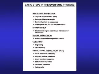
Course Content • Fire Sprinkler System Types • Responsibility of the Inspector • Review of Standard Annual Inspection • 3 Year Inspections • 5 Year Inspections • 10 Year Inspections • Obstruction Inspection / Investigation • Standpipe Tests and Inspections • Fire Pump Tests and Inspections
Types of Sprinkler Systems • Wet Type Systems • Dry Type Systems • Pre-action Type Systems • Deluge Systems
Wet System • System piping filled completely with water • Sprinklers discharge water immediately once the sprinkler element is activated or fused upon reaching their head temperature listing • Most common form of fire protection system • Typical applications: office buildings, warehouses, schools, etc. • Per NFPA 13, an area must be maintained above 40 degrees Fahrenheit or else another system must be provided (i.e. Dry, Pre-action or Deluge)
Wet System Butterfly Valve Riser Manifold
Dry System • Air or nitrogen under pressure holds back water at dry pipe valve. When sprinkler element is fused, air (or nitrogen) is released from system piping allowing the dry pipe valve to open. • A larger remote area is required to be calculated due to the delay in time it takes for the water to get to the fire. The fire will be larger so more water is necessary. • Used in occupancies where there is not adequate heat, such as, attics, canopies, garages, etc.
Basic Dry Pipe Valves • Simplest form of dry type systems • Requires water supply, dry pipe valve and compressed air or nitrogen supply • No form of electric or pneumatic detection required System Operation • Air pressure maintained in piping holds dry pipe valve clapper in closed position • Most dry valves have a water to air pressure ratio of 5:1 (5 psi water : 1 psi air). Low pressure type have up to 12:1 differential. • Sprinkler activation releases air pressure and allows the clapper in the dry valve to open
Clapper Intermediate chamber Intermediate chamber Dry Pipe Valve Schematic
Pre-action System • System employing automatic sprinklers attached to a piping system that may or may not contain pressurized air • Activated upon release of supplemental detection which opens a valve to release water • Single Interlocked: • System piping is dry • Water will only enter system upon heat/smoke detection activation • Higher level of protection then a dry system • Typical applications include: Computer rooms, MRI rooms, etc.
Double interlocked: • System piping is dry • Water will only enter system upon heat/smoke detection as well as a sprinkler fusing which will permit the air in the piping to be discharged from system thus allowing the valve to open. • Highest level of protection • Typical applications include: Freezers, and other areas where water cannot be discharged unless there is a fire.
Deluge/Pre-action Valve To release system (pneumatic actuator, solenoid valve, and manual pull station)
Pre-action Riser Schematic Water supply to priming chamber through restricted orifice Control valve
Non-interlock Electric / Pneumatic Release Electric solenoid System air pressure To drain To drain Pneumatic actuator Pressure from priming chamber of deluge valve Activation of a sprinkler or the electric detection will cause the deluge (preaction) valve to open. An open sprinkler relieves air pressure from the system side of the pneumatic actuator which allows the pneumatic actuator to open and relieve pressure from the priming chamber of the deluge valve. Electric detection operates the solenoid valve to relieve pressure from the priming chamber of the deluge valve.
Single Interlock, Electric Release Solenoid valve To drain Pressure from priming chamber of deluge valve Activation of the electric detection opens the solenoid valve which relieves air pressure from the priming chamber of the deluge valve, allowing the clapper of the deluge valve to open and water to enter the system. Compressed supervisory air is maintained in the sprinkler piping to initiate an alarm if piping or sprinklers break or fail.
Double Interlock Electric / Pneumatic Release To drain Pneumatic actuator Solenoid valve Pressure from priming chamber of deluge valve System Air Pressure ½” x 1 ½” nipple Both sprinkler activation and detection activation are required to operate a double interlock system. Operation of detection opens the solenoid valve, but pressure is still held in the priming chamber until operation of a sprinkler relieves air pressure from the pneumatic actuator which allows the pneumatic actuator to open and relieve pressure from the priming chamber of the deluge valve through the pneumatic actuator to drain.
Deluge System • Piping is dry • Sprinklers are always open (sprinkler elements have been removed) • Detection in the form of a pilot line system, or electric detection will permit water to enter the piping and flow from the open sprinklers immediately. • Pneumatic operation (pilot line) incorporates a separate piping network filled with compressed air with special releasing devices • This type of system is what is typically shown in Hollywood movies • Typical applications include: Transformers, ethanol plants, cooling towers, and other high hazard occupancies
Deluge Valve To sprinklers To release system (pneumatic actuator, solenoid valve, and manual pull station) The priming chamber is pressurized with water through a restricted orifice from the supply side of the control valve holding clapper (6) closed against rubber seat (8). The clapper is suspended on rubber diaphragm (2). When pressure is relieved by the releasing system, the clapper rises, allowing water to enter the outlet chamber. Supply
Responsibility of the Inspector ****Contact the alarm company**** The inspection of a fire sprinkler system is strictly limited to the operational readiness and integrity of the system. NFPA 25 does not require the inspection to include investigation for Code violations or design deficiencies. The question that must be answered at the end of an inspection is: Will the system operate as intended if a fire should occur?
Visually Inspect the System • A visual inspection of the system from the floor is a clearly defined limit in NFPA 25 • Sprinklers • Pipe and fittings • Hangers • Seismic bracing/restraints • Components in areas that are not accessible do not require inspection • Above suspended ceilings • Inaccessible areas below floors • Inaccessible attics • Inaccessible rooms
Owner’s Responsibility “The responsibility for properly maintaining a water-based fire protection system shall be that of the owner of the property.” As the inspecting contractor, we can only make recommendations for needed repairs or replacement. It is ultimately the owner’s responsibility to assure the work is completed.
Impairment If at any time during the inspection it becomes obvious that the system will not operate, then immediately terminate the inspection, red tag the control valve and fire department connection “System Out of Service”, and contact your supervisor or office. This includes fire pumps that are out of service. It is the owners responsibility to contact their insurance company, alarm company and AHJ.
Standard Inspection Report • All of these questions are to be answered by the owner. • If the occupancy has changed, make detailed note on report. This is not necessarily a deficiency nor is it your responsibility to do a design evaluation. • Describe any modifications that may have been made including relocated walls.
B. Examples of obstructions include storing product to close to sprinklers on shelving; ducts, overhead doors, hanging signs, unit heaters, etc. E. & F. See 10 year testing schedule for older sprinklers G. Solder link sprinklers in cooking ventilation systems must be replaced every year
N. If it is not obvious that building additions or alterations are properly protected, then note this on a separate sheet. Design evaluations are not part of a regular inspection. O. ESFR and large drop sprinklers require a minimum clearance of 36” from deflector to top of storage. All others require 18”. P. Make notation on this line if the system is pipe schedule sizing and not hydraulically designed. Q. Sprinklers manufactured before 1920 must be replaced.
In addition to the above, a fire department connection • must have unobstructed access and there must be enough • room to manipulate a spanner wrench on the couplings.
A separate backflow preventer test report must be • completed for each assembly.
Antifreeze systems should have a sign indicating the • location of the system, type of antifreeze, system capacity • and antifreeze-water mixture. • Must use glycerin in CPVC pipe. • No new antifreeze will be installed due to new NFPA • code requirements. No “listed” antifreeze available on the • market.
NFPA requires air supplies from a “reliable” source, but it • is not defined. If the compressor has a plugged or • switched connection, then this is a deficiency. The • compressor should be hard wired to any available circuit. It • does not have to be on emergency power.
The electric, pneumatic or hydraulic releasing system with • deluge and preaction valves must be part of the inspection • to assure operation of the system. Electric detection must • be tested by a qualified technician.
If alarms are monitored at a remote location, then verify • that flow and supervisory alarms were received. • Supervision of alarms at a remote location may or may • not be a code issue. The lack of supervision should be • noted. • Local water flow alarms must operate within 5 minutes of • water flow, or 90 seconds to alarm service.
Control valves should be locked in the open position at a • minimum, but electric supervision is preferred.
Main drain tests must be conducted on every system in the facility. • Main drain tests must be compared to all previous tests and when a 10% reduction in static and/or residual flow pressures are observed, then an obstruction investigation must be recommended. • Main drain tests must be conducted with the normal water supply with fire pumps in service.
If there is any type of impairment that prevents the system from operating and corrective action is not taken immediately, then contact the office or your supervisor. Red tag the riser and fire department connection “System Out of Service”.
Comment Categories • Impairment: Any failure of a component that would prevent operation of the system, including pumps that are out of service. Terminate inspection and follow impairment procedure. • Deficiency: Any condition, component or item that may impede the ability of the system to control a fire, but will not prevent the system from operating. Examples include obstructions to sprinkler discharge, minimum clearances not maintained, no 3, 5 or 10 year inspections, the need for a design evaluation by a design professional, etc.
3 Year Inspections • Fire hose to be tested at 3 year intervals if over 5 years old • Full flow trip test of dry and preaction valves • AHJ (Authority Having Jurisdiction) can modify and accept lesser requirements than NFPA 25 code
5 Year Inspections • Interior of all valves, strainers, filters and orifices on trim • Interior of preaction and deluge valves with external reset capabilities, strainers, filters and orifices on trim • Standpipe and Hose Systems • Hose connections and hose rack (if still in service). • Hydrostatic test of standpipe and hose systems • Flow test standpipe and hose systems • Obstruction inspection (not investigation) • Replace or test gauges for accuracy
10 Year Inspection All tests and inspections listed under 5 years in addition to the following: • Test or replace dry sprinklers at 10 year intervals • Verify that fast or quick response sprinklers that are 20 years old or older have been tested at 10 year interval • Verify that standard response sprinklers that are 50 years old or older have been tested at 10 year interval
Sprinkler Testing • Sample sprinklers taken for testing shall consist of 4 sprinklers or 1% of sprinklers in an area, whichever is greater • Cannot use sprinklers in head cabinet as test sample • Quick or fast response sprinklers to be tested at 20 years • Standard sprinklers to be tested at 50 years
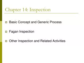
Obstruction Inspection vs. Investigation Chapter 14 of NFPA 25 describes two distinctly different activities relating to obstructions in sprinkler systems. An obstruction inspection is required at 5 year intervals and is intended to be very minimal to avoid lengthy system outage. It should be conducted at the same time as the required 5 year interior inspection of control valves, alarm valves, dry valves etc. Inspections are intended to reveal potential problems that would require a more thorough investigation procedure.
Obstruction Investigation When an obstruction inspection reveals a potential problem, then a more in-depth obstruction investigation must be conducted. The extent of the investigation is dictated by the suspected obstruction material and will require detailed pre-planning to minimize system downtime and still achieve the desired results. Investigation procedures are described in Annex D of NFPA 25.
Standpipe Flow Testing Preplanning a standpipe flow test is critical. The following guidelines are based on perfect conditions that seldom exist. Review options with a design manager to achieve the best results toward satisfying the intent of the code. • Number of standpipes to flow? • Most remote and highest standpipe to flow 500 gpm • Each additional standpipe to flow 250 gpm • Maximum 4 standpipes or 1250 gpm in non-sprinklered building • Maximum 3 standpipes or 1000 gpm in fully sprinklered building • i.e. 500 GPM (Most Remote), 250 GPM, 250 GPM
Where will water discharge? • Is there adequate drainage • How many lengths of hose will be required • Are pressure gauge outlets on the top of all standpipes? • Use good test gauges • Gauge outlets that are directly across from hose valves will not give accurate readings. • Is there a pump or pumps? • Suction and discharge readings must be taken simultaneously with pressure readings at the top of standpipes • Churn readings and flow readings • Take pressure readings at water main entrance to building • Results of standpipe tests must be reviewed by a designer
Know the type of pump and driver • Diesel or electric • Horizontal shaft split cast centrifugal • Vertical shaft in-line centrifugal • Vertical shaft turbine Pump TestingPreparation
Horizontal Split Case Centrifugal Jockey Pump
Water discharge location • Tachometer – do not rely on engine mounted tachometer • Pitot tube with 0 – 100 psi liquid filled gauge • Voltage and amperage gauge • Calibrated pump discharge and suction pressure gauges • Test forms to include factory certified pump test curve (if available)
Pre-test Functions • Record pump data plate information • Record driver data plate information • Record controller data plate information • Check driver coupling alignment • Does pump have a flow meter or test header or both
Verify proper placement of suction and discharge gauges • Notify alarm company • Isolate fire protection system from pump discharge • Confirm supply pipe control valves are open • Components are properly lubricated