Data Communication and Networking
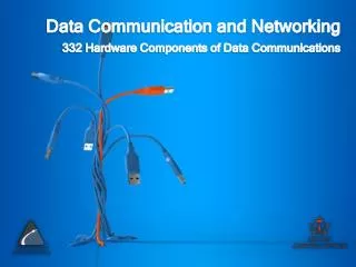
Data Communication and Networking. 332 Hardware Components of Data Communications. Lecture Overview. Shift Register Buffering Direct Memory Access. Shift Register.

Data Communication and Networking
E N D
Presentation Transcript
Data Communication and Networking 332 Hardware Components of Data Communications
Lecture Overview • Shift Register • Buffering • Direct Memory Access
Shift Register • A shift register is a sequential logic device made up of flip-flops that allows parallel or serial loading and serial or parallel outputs as well as shifting bit by bit • The Shift Register is used for data storage or data movement and are used in calculators or computers to store data such as two binary numbers before they are added together, or to convert the data from either a serial to parallel or parallel to serial format • The data bits may be fed in or out of the register serially, i.e. one after the other from either the left or the right direction, or in parallel, i.e. all together
Characteristics of Shift Register • Number of bits (4-bit, 8-bit, etc.) • Loading • Serial • Parallel (asynchronous or synchronous) • Common modes of operation. • Parallel load • Shift right-serial load • Shift left-serial load • Hold • Clear
Parallel out Serial out Serial out Serial in 1 0 1 0 1 1 1 1 1 0 1 0 1 1 1 1 1 0 1 0 1 1 1 1 1 0 1 0 1 1 1 1 Parallel out Parallel in Parallel in Serial in Shift Register Modes • Some basic data movements are illustrated here.
Shift Register Modes • Serial-in to Parallel-out (SIPO) - the register is loaded with serial data, one bit at a time, with the stored data being available in parallel form. • Serial-in to Serial-out (SISO) - the data is shifted serially "IN" and "OUT" of the register, one bit at a time in either a left or right direction under clock control. • Parallel-in to Serial-out (PISO) - the parallel data is loaded into the register simultaneously and is shifted out of the register serially one bit at a time under clock control. • Parallel-in to Parallel-out (PIPO) - the parallel data is loaded simultaneously into the register, and transferred together to their respective outputs by the same clock pulse.
Buffering • A computer buffer is an area of memory used for the temporary storage of data when a program or hardware device needs an uninterrupted flow of information • Buffers are typically created in Random Access Memory (RAM) rather than on the hard disk
Buffering Examples • Buffers are commonly used when burning data onto a compact disc, where the data is transferred to the buffer before being written to the disc. • Another common use of buffers is for printing documents. When you enter a PRINT command, the operating system copies your document to a print buffer (a free area in memory or on a disk) from which the printer can draw characters at its own pace. This frees the computer to perform other tasks while the printer is running in the background
Direct Memory Access • Direct Memory Access (DMA) is a method of allowing data to be moved from one location to another in a computer without intervention from the central processor (CPU). • The microprocessor is freed from involvement with the data transfer, thus speeding up overall computer operation. • Many hardware systems use DMA, including disk drive controllers, graphics cards, network cards and sound cards. • Computers that have DMA channels can transfer data to and from devices with much less CPU overhead than computers without a DMA channel
Direct Memory Access Modes • Single • A single byte (or word) is transferred. • The DMA must release and re-acquire the bus for each additional byte. • This is commonly-used by devices that cannot transfer the entire block of data immediately. • The peripheral will request the DMA each time it is ready for another transfer.
Direct Memory Access Modes • Burst Mode • An entire block of data is transferred in one contiguous sequence. • Once the DMA controller is granted access to the system bus by the CPU, it transfers all bytes of data in the data block before releasing control of the system buses back to the CPU. • This mode is useful for loading program or data files into memory, but renders the CPU inactive for relatively long periods of time • The mode is also called "Block Transfer Mode".
Direct Memory Access Modes • Cycle stealing mode • The cycle stealing mode is used in systems in which the CPU should not be disabled for the length of time needed for burst transfer modes. • In the cycle stealing mode, the DMA controller obtains access to the system bus the same way as in burst mode, using BR (Bus Request) and BG (Bus Grant) signals, which are the two signals controlling the interface between the CPU and the DMA controller. • However, in cycle stealing mode, after one byte of data transfer, the control of the system bus is disserted to the CPU via BG. • It is then continually requested again via BR, transferring one byte of data per request, until the entire block of data has been transferred. • By continually obtaining and releasing the control of the system bus, the DMA controller essentially interleaves instruction and data transfers. • The CPU processes an instruction, then the DMA controller transfers one data value, and so on. • Cycle stealing mode is useful for controllers that monitor data in real time.
Direct Memory Access Modes • Transparent mode • The transparent mode takes the most time to transfer a block of data, yet it is also the most efficient mode in terms of overall system performance. • The DMA controller only transfers data when the CPU is performing operations that do not use the system buses. • It is the primary advantage of the transparent mode that the CPU never stops executing its programs and the DMA transfer is free in terms of time. • The disadvantage of the transparent mode is that the hardware needs to determine when the CPU is not using the system buses, which can be complexes.