Download

1 / 14
210 likes | 388 Views
Car Jack Mast Design Update. Presented by Doug Eddy and Dr. Sundar Krishnamurty at UMass Amherst for Hoppe Tool on 7/16/10. Control of Scissors’ Motion. This mechanism is under constrained. Potential Remedy.

E N D
Car Jack Mast Design Update Presented by Doug Eddy and Dr. Sundar Krishnamurty at UMass Amherst for Hoppe Tool on 7/16/10
Control of Scissors’ Motion This mechanism is under constrained.
Potential Remedy • Theoretically, the bottom pivots far apart shortens travel and close together affects stability.
Alignment without Binding Connecting links needed between center pivots How well will the 3 sides move together and keep top in line with bottom?
Consider an actual Car Jack Design The screw is horizontal and moves up and down during lifting.
Consider a Conventional Scissor Lift The shape is rectangular. Parallel scissors are rigidly connected at outer pivots. Legs are made of rectangular tubing for strength and stability.
Engineering Analysis • A simplified explanation is found at: • http://www.engineersedge.com/mechanics_machines/scissor-lift.htm • The information is verified and correct. • This reveals a design challenge with the multiscissor arrangement. • The screw force required is very large when the angle is small at the start of lifting. • The threshold power spec is 850 Watts. • Mechanical advantage with unequal scissor’s lengths is only 15-35%.
Car Jack Potential Design Remedies • Longer scissors’ length • Increase retract height and scissor start angle • Longer pitch lead of screw and nut length • Must also minimize friction and consider those effects • Clevis mounted angle optimized drive pivot mount?
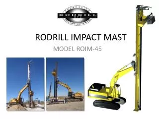
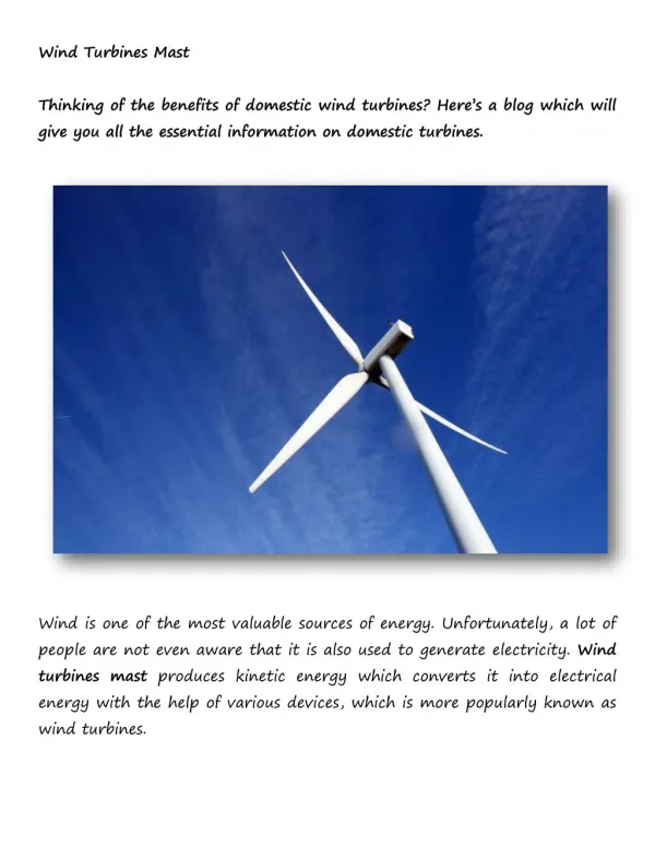
Strap Design 8m mast supporting 120kg (EW system)
Claims of the Belt Design • LERC S.A. • BP 10119 – 59732 SAINT AMAND LES EAUX CEDEX – France • Tel: +33 3.27.22.85.50 – Fax: +33 3.27.22.85.55 – e-mail: commercial@lerc.fr • Internet: www.lerc-composites.com • Page 2/4 • Main Advantages • • Resistance to bullet impacts: a bullet impact on a pneumatic mast • manufactured from light alloy or pultruted composite will make a hole that • will result in an air leak and in the mast collapse. It will also make a slight • crack in the matrix likely to break the tube. In a belt drive telescopic mast, • a bullet impact (see picture) will make a hole without affecting the mast • height. Moreover, the woven and crossed structure (Filament Winding - • FW) of the composite material prevents any crack in the tube. • • Height maintained at constant level when the mast is in erection for • an extended time : a pneumatic mast tends to go flat and therefore to • retract, which can result in a cutting off of the radio contact. • • Outstanding resistance to corrosion, chemical attacks and ageing ; • • Undeformability: the tube sections show no permanent deformation even after extensive use (strength • maintained, no ovalizing); • • Best ratio between deployed and retracted heights • • Lightweight and outstanding mechanical resistance • • No maintenance other than wiping or brushing to clean and for the telescopic masts, replacement of the • belt without dismounting tubes (can be performed on the field). • • Excellent resistance to environmental conditions (use of Epoxy resin and FW process): Sand, dirt, • dust, snow, ice will not cause degradation of mast performance. On mast with the new belt system, the belt • is fully inside the mast, protected against outside environment. • • No air tightness to ensure : no adjustments to make height maintained at constant level ; • • Manipulation with naked hands, even under cold or hot temperature ; • • Adaptability to the customer’s needs : the mast structure is computer designed (SAMCEF method) • • LERC proven experience: close to 60 years in the field of composite materials, 30 years in the • manufacturing of tactical masts and antennas.
Design Concerns with Strap Concept • Resistance of bending around small pins • Possibility of slipping at speed desired if not enough tension • Contact area on small pins • Power required increases with tension and the number of pulley contacts for simultaneous lifting.
Question for you? • How do you and the customers rank or weight the various features?: • Low power required • Small area, length • Low weight • High reliability and strength • Low sway and deflection, high stability • Low start height • High extended height • Low cost • High payload capability • High speed capability • High center clearance area and proximity for the cabling and basket below
Consider a Simple Straight Pulley Lift Work output = mgh = 45 pound payload x 20 feet lifting height = 900 lb - ft If the total system mechanical efficiency were 64% (although not realistic , for a system lifting from underneath) Work input needed = 900 / 0.64 = 1406 lb – ft = F x d = System pull force x System pull distance This must be done within 15 seconds, Power = Work done per unit time = 1406 / 15 = 93.75 ft – lbf / second 550 ft – lbf / sec = 1 Hp, so for a 93% efficiency motor 93.75 / (550 *0.93) = 0.183 Hp = 137 Watts