Download

1 / 25
250 likes | 329 Views
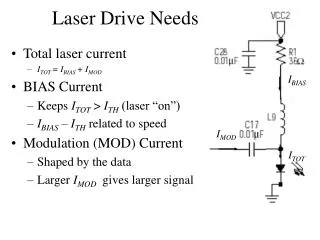
XFEL Short Bunch Measurement and Timing Workshop. LCLS Drive Laser Timing Stability Measurements. X -. X-band. LCLS Machine Stability Tolerance Budget. 800fS rms.

E N D
XFEL Short Bunch Measurement and Timing Workshop LCLS Drive Laser Timing Stability Measurements
X- X-band LCLS Machine Stability Tolerance Budget 800fS rms RMS tolerance budget for <12% rms peak-current jitter or <0.1% rms final e− energy jitter. All tolerances are rms levels and the voltage and phase tolerances per klystron for L2 and L3 are Nk larger, assuming uncorrelated errors, where Nk is the number of klystrons per linac. P. Emma
LINAC RF and Timing System Master Oscillator is located 1.3 miles from LCLS Injector 1.3 Miles to LCLS Injector PEP PHASE SHIFT ON MAIN DRIVE LINE MDL RF with TIMING Pulse – Sync to DR
Linac Phase Reference System • Main Drive Line - 3 1/8 Rigid Coax Anchored to Concrete Floor Every Sector • Phase Reference Line - Each Sector Independent 1/2 “ Heliax
Linac Phase Reference System • Phase Reference Line • ½ inch Heliax Cable with 1.2 Watts • Phase Reference for 8 PADs (Klystrons) in the sector • Length = 1 Sector, 0.5 furlongs, 332ft, 400kS in ½” Heliax • Temperature Coefficient 4ppm/C • Waveguide Water T = 0.1C rms • 85% of the cable is regulated to 0.1C rms • 15% may see variations of 2C rms • Average Temperature Variation = 0.4C rms • = 0.64S rms • Main Drive Line • 3 1/8 inch Rigid Coax with 30watts • Length = 31 Sectors, 15.5 furlongs 2miles, 3km : Velocity = 0.98c • Anchored at each sector next to coupler and expansion joint • Purged with dry nitrogen • Phase Length Range 100S/Year • Phase Length Range 40S/Day • Accuracy Based on SLC Fudge Factor • 0.5S/Sector Total Variation • 0.2S rms / Sector
Phase Noise of SLAC Main Drive LineOld Oscillators Noise Floor of About -120dBc/38Hz = -136dBc/Hz = 120fS rms Jitter in 5MHz BW
Phase Noise of SLAC Main Drive LineNew Oscillators Noise Floor of About -133dBc/38Hz = -149dBc/Hz < 60fS rms Jitter in 5MHz BW New Oscillators Have a noise floor of -157dBc/Hz @ 476MHz 11fS rms Jitter in 5MHz BW or 31fS rms Jitter in 40MHz BW Above plots give upper limits, much of which could be from measurement system
SLAC Linac RF The PAD measures phase noise between the reference RF and the high power system. The beam sees 3.5uS of RF from SLED.
LINAC RF MEETS ALL LCLS SPECIFICATIONS for 2 Seconds when running well Amplitude fast time plots show pulse to pulse variation at 30Hz. Standard deviation in percent of average amplitude over 2 seconds are 0.026% for 22-6 and 0.036% for 22-7. Phase fast time plots show pulse to pulse variation at 30Hz. Standard deviation in degrees of 2856MHz over 2 seconds for the three stations are 0.037 for 22-6 and 0.057 for 22-7.
LINAC RF is Out of LCLS Specs in 1 Minute Phase 22-6 1.2 Deg pp Amplitude 22-6 0.20%pp Amplitude 22-7 0.43%pp Phase 22-7 1.2 Deg pp 14 minutes data taken using the SCP correlation plot Note that 22-6 and 22-7 are correlated in phase and amplitude
Phase as Seen by Electron is Difficult to Measure Accelerator Water Temperature Effects on SLED Phase[1] The tuning angle of the SLED cavity goes as: = tan -1 (2QLT), Where T = L/L = -/ QL= 17000 = 10-5 / F Thermal expansion of copper. =tan -1 (0.34T) Where T is in F. For small T, (S)= 20T(F) The relation between the tuning angle and the measured output phase of the klystron varies with the time after PSK with about the following relation: / = 0.35 just after PSK (S)= 7T(F) / = 0.50 800nS after PSK (S)= 10T(F) / T~ +8.5 S / F for SLED Cavity Accelerator Water Temperature Effects on the Accelerator Phase[2] The phase change of the structure goes as follows: = f Where = phase through structure = Angular frequency f = Filling time of structure = f = / x f/ = -L/L = -T = -10-5 T / F for copper = -10-5 T / F22856MHz0.84S = -0.15 T rad/F = -8.6 T S / F / T = -8.6 S / F for Accelerator Structure Water / Accelerator Temperature Variation is 0.1F rms through structure is 0.86F rms [1] Info from D. Farkas [2] Info from P. Wilson
Phase as Seen by Electron is Difficult to Measure • Accelerator Water Temperature Effects on the Phase Through the Accelerator-8.6 S / F • SLAC Linac Accelerator Water TemperaturesT< .08Frms • Phase Variations Input to Output of Accelerator > 0.5ºS-Band rms • Single Measurement Can’t Determine the Phase the Beam Sees Passing Through the Structure to LCLS Specifications • Feedback on Input Phase, Output Phase, Temperature, Beam Based Parameters (Energy and Bunch Length) is Required to Meet LCLS Specifications
LINAC SECTOR 20 – LCLS INJECTOR RF Stability < 50fS rms : Timing/Trigger Stability 30pS rms
LCLS RF System – Sector 20 Layout 100ft ½” Heliax = 0.3ºS/ºF Tunnel Temperature < 0.1deg F rms
SPPS Laser Phase Noise Measurement R. Akre, A. Cavalieri
SPPS Laser Phase Noise Measurements Phase Noise of Output of Oscillator with Respect to Input Measurement done at 2856MHz with External Diode R. Akre, A. Cavalieri
SPPS Laser Phase Jump Tracking R. Akre, A. Cavalieri
SPPS Laser Phase Jump Tracking Laser Phase Error – Output Phase to Input Reference - Modulated with 1 Hz Square Wave 0.25pS pk Square Wave 0.25pS pk Square Wave
SPPS Laser Amplitude of Phase Transfer Function Phase Modulation placed on RF Reference and measured on Diode at Laser output. During the Blue part of the curve the modulation amplitude was reduced by 12dB to prevent laser from unlocking. Data taken 10/22/03 R. Akre, A. Cavalieri
SLAC Linac 1 GeV 30 GeV e- Energy (MeV) Linac Phase Stability Estimate Based on Energy Jitter in the Chicane BPM 9 GeV sE/E0 0.06% Df 21/2< 0.1 deg (100 fs) P. Emma
Jitter determination from Electro Optic sampling • Cavalieri • P. Krejcik Principal of temporal-spatial correlation single pulse Line image camera EO xtal analyzer polarizer Er width centroid 30 seconds, 300 pulses: sz = 530 fs ± 56 fs rms Dt = 300 fs rms
Electro-Optical Sampling Timing Jitter (20 Shots) 200 mm thick ZnTe crystal Single-Shot e- <300 fs Ti:Sapphire laser e- temporal information is encoded on transverse profile of laser beam 170 fs rms Adrian Cavalieri et al., U. Mich.
LCLS Phase Noise Associated Time Referenced to Beam Time • LCLS Laser Need to Measure • 10uS to 1mS ~200uS • LCLS Gun 1.1uS • SLED / Accelerator 3.5uS • Phase Detector (Existing) 30nS • Distribution System 200nS • 1km @ c-97%c=100nS • Far Hall Trigger 2uS • 3km @ c-80%c=2uS -3.5us SLED Starts to Fill -2uS Far Hall Trig RF Starts Trip -1.1uS Gun Starts to Fill Beam Time 0 Reference TIME
Beam Trigger for User Facility • Single Pulse with 30fS stability (1Hz to 3GHz BW) • Tightest Noise Tolerance of LCLS • Wide Bandwidth – Narrow Bandwidth • ECL chips have 150pS rise times • Low Phase Noise • 30fS Stability today • 10fS Stability tomorrow • 1fS ??? • Design Needs Input