Ant Brain State Minimization Assignment Overview
The assignment delves into state minimization for Ant Brain circuit, explaining sequential logic, Mealy/Moore machines, and designing the brain. Learn about defining states, transition truth tables, K-maps, and circuit implementation.


Ant Brain State Minimization Assignment Overview
E N D
Presentation Transcript
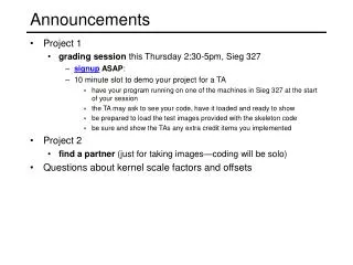
Announcements • Assignment 8 posted • Due Friday Dec 2nd. A bit longer than others. • Project progress? • Dates • Thursday 12/1 review lecture • Tuesday 12/6 project demonstrations in the lab (no presentations) • Sunday 12/11 project reports due to me by email • Tuesday 12/13 final exam, 1pm-3pm here.
Lecture 23 Overview • More Sequential Logic • Ant Brain Example • State Minimization • Mealy/Moore Machines
Example: Ant Brain (Ward, MIT) • Sensors: L and R antennae, 1 if in touching wall • Actuators: F - forward step, TL/TR - turn left/right slightly • Goal: find way out of maze • Strategy: Wall follower: keep the wall on the right: walk through the maze, tapping the wall with the right antenna. end start
Ant Brain: Defining the states • We need to turn the strategy into an algorithm - define a series of states and the appropriate response to them. • Special case I : Left antenna touching the wall • Turn 180 degrees - turn left until right antenna no longer touches the wall.
Ant Brain: Defining the states • Special case II : No antenna touching the wall • Ant lost - go straight forward
Ant Brain Complete instruction set: describes the instructions required for the ant to walk through the maze, tapping the wall with its right antenna B: Following wall, not touching Go forward, turning right slightly A: Following wall, touching Go forward, turning left slightly D: Hit wall again Back to state A State D is the same as state A C: Break in wall Go forward, turning right slightly E: Wall in front Turn left until... F: ...we are here, same as state B State F is the same as State B G: Turn left until... State G is effectively the same as State E LOST: Forward until we touch something
L + R L’ R LOST (F) E/G(TL) A (TL, F) L + R L R L’ R’ L’ R’ R L’ R’ B (TR, F) C(TR, F) R’ R’ Designing an Ant Brain • Draw the State Diagram • Transition arrows represent input from antennae • Actuators F=forward step, TL=turn left slightly, TR=turn right slightly
Synthesizing the Ant Brain Circuit • Encode States Using a Set of State Variables • The encoding is an arbitrary choice - may affect cost, speed • Use Transition Truth Table • Define next state function for each state variable • Define output function for each output • Implement next state and output functions using combinational logic
L + R L’ R state L R next state current outputs LOST 0 0 LOST F LOST – 1 E/G F LOST 1 – E/G F A 0 0 B TL, F A 0 1 A TL, F A 1 – E/G TL, F B – 0 C TR, F B – 1 A TR, F ... ... ... ... ... LOST (F) E/G(TL) A (TL, F) L + R L R L’ R’ L’ R’ R L’ R’ B (TR, F) C(TR, F) R’ R’ Transition Truth Table • First, using symbolic states and outputs, derive the transition truth table
Synthesis LOST - 000 E/G - 001 A - 010 B - 011 C - 100 • 5 states : 3 state variables required (X, Y, Z) • State assignment: • Convert symbolic states to bits (in this case, arbitrarily chosen) • Also represent outputs with bits it now remainsto "synthesize"these 6 functions: to design output logic and next state logic to produce this result state L R next state outputs X,Y,Z X', Y', Z' F TR TL 0 0 0 0 0 0 0 0 1 0 0 0 0 0 0 1 0 0 1 1 0 0 ... ... ... ... ... 0 1 0 0 0 0 1 1 1 0 1 0 1 0 0 1 0 1 0 1 0 1 0 1 0 1 0 0 0 1 1 0 1 0 1 0 1 1 0 0 1 1 0 1 0 1 1 0 0 1 0 0 1 1 0 0 1 1 0 1 0 1 0 1 1 0 ... ... ... ... ... An alternative Assignment: LOST - 000 E/G - 101 A - 110 B - 111 C - 100
Synthesis of Next State and Output Functions solve (using K-maps) for each output and next state e.g. TR = X + Y Z X+ = X R’ + Y Z R’ = R’ TR state inputs next state outputs X,Y,Z L R X+,Y+,Z+ F TR TL 0 0 0 0 0 0 0 0 1 0 0 0 0 0 - 1 0 0 1 1 0 0 0 0 0 1 - 0 0 1 1 0 0 0 0 1 0 0 0 1 1 0 0 1 0 0 1 - 1 0 1 0 0 0 1 0 0 1 1 - 0 1 0 0 0 1 0 1 0 0 0 0 1 1 1 0 1 0 1 0 0 1 0 1 0 1 0 1 0 1 0 1 - 0 0 1 1 0 1 0 1 1 - 0 1 0 0 1 1 0 0 1 1 - 1 0 1 0 1 1 0 1 0 0 - 0 1 0 0 1 1 0 1 0 0 - 1 0 1 0 1 1 0 3 state bits + 2 inputs means 25 = 32 rows in the transition table. Here we only show those we care about. e.g.: Unused states 101, 110 & 111 are missing Assumed don't cares
F TR TL outputlogic next statelogic Next State L R X+ Y+ Z+ Current State X Y Z Circuit Implementation • Outputs are a function of the current state only • Moore machine state inputs next state outputs X,Y,Z L R X+,Y+,Z+ F TR TL 0 0 0 0 0 0 0 0 1 0 0 0 0 0 - 1 0 0 1 1 0 0 0 0 0 1 - 0 0 1 1 0 0 0 0 1 0 0 0 1 1 0 0 1 0 0 1 - 1 0 1 0 0 0 1 0 0 1 1 - 0 1 0 0 0 1 0 1 0 0 0 0 1 1 1 0 1 0 1 0 0 1 0 1 0 1 0 1 0 1 0 1 - 0 0 1 1 0 1 0 1 1 - 0 1 0 0 1 1 0 0 1 1 - 1 0 1 0 1 1 0 1 0 0 - 0 1 0 0 1 1 0 1 0 0 - 1 0 1 0 1 1 0
L’ R’ L + R L’ R 000 (F) 001(TL) 010 (TL, F) L L + R 101 R L’ R’ R L’ R’ 011 (TR, F) 100(TR, F) 110 R’ 111 R’ Don’t Cares in FSM Synthesis • What happens to the "unused" states (101, 110, 111)? • They can be exploited as don't cares to minimize the logic • If these states can't happen, then we don't care what the functions do • if these states do happen, we may be in trouble Ant is in deep trouble if it gets in this state
State Minimization • Fewer states may mean fewer state variables • High-level synthesis may generate many redundant states • Two states are formally equivalent if they are impossible to distinguish from the outputs of the FSM, i. e., for any input sequence the outputs are the same • Two conditions for two states to be equivalent: • Output must be the same in both states (The nodes in the state diagram must be the same) 2) Must transition to equivalent states for all input combinations (The arrows FROM the nodes in the state diagram must result in the same state)
L + R L’ R LOST (F) E/G(TL) A (TL, F) L + R L R L’ R’ L’ R’ R L’ R’ B (TR, F) C(TR, F) R’ R’ Ant Brain Revisited • Two conditions for two states to be equivalent: • Output must be the same in both states (The nodes in the state diagram must be the same) 2) Must transition to equivalent states for all input combinations (The arrows FROM the nodes in the state diagram must result in the same state) • Any more equivalent states?
L + R L’ R LOST (F) E/G(TL) A (TL, F) L + R L R L’ R’ L’ R’ L’ R’ B/C (TR, F) R’ New Improved Brain • Merge equivalent B and C states • Behavior is exactly the same as the 5-state brain • We now need only 2 state variables rather than 3
L + R L’ R LOST (F) E/G(TL) A (TL, F) L + R L R L’ R’ L’ R’ L’ R’ B/C (TR, F) R’ New Improved Brain Only 2 state variables:
state inputs next state outputs X,Y L R X+,Y+ F TR TL 0 0 0 0 0 0 1 0 0 0 0 - 1 0 1 1 0 0 0 0 1 - 0 1 1 0 0 0 1 0 0 1 1 0 0 1 0 1 - 1 0 1 0 0 1 0 1 1 - 0 1 0 0 1 1 0 0 0 1 1 1 0 1 1 0 0 1 1 0 1 0 1 1 0 1 - 0 1 1 0 1 1 1 - 0 1 1 1 1 0 1 1 - 1 1 0 1 1 0 X X X X X TR TL Y+ F X+ 0 1 1 1 0 0 1 1 0 0 1 0 0 0 1 0 0 1 0 1 0 1 0 1 0 1 0 1 0 1 0 1 0 1 1 1 1 0 0 0 1 0 0 1 1 0 1 1 0 0 1 0 0 0 1 0 0 0 1 0 0 0 1 0 1 0 1 1 1 0 1 1 1 0 1 1 1 0 1 1 R R R R R L L L L L Y Y Y Y Y New Brain Implementation Karnaugh Maps: Use these to derive combinational logic for next state Use these to derive combinational logic for outputs (only depends on X & Y)
L’ R / TL, F A L / TL L’ R’ / TR, F Mealy vs. Moore Machines • Moore: outputs depend on current state only • Mealy: outputs depend on current state and inputs • Ant brain is a Moore Machine • Internal state defines the outputs • Output does not react immediately to input change • We could have specified a Mealy Machine • Outputs have immediate reaction to inputs • As inputs change, so does next state, doesn’t commit until clocking event react right away to leaving the wall
0 1 D/1 B/0 0 0 reset 1 0 A/0 1 1 E/1 C/0 0 1 Specifying Outputs for a Moore Machine • Output is only function of state • Specify output in state bubble in state diagram • Example: sequence detector for 01 or 10 current next reset input state state output 0 0 A B 0 0 1 A C 0 0 0 B B 0 0 1 B D 0 0 0 C E 0 0 1 C C 0 0 0 D E 1 0 1 D C 1 0 0 E B 1 0 1 E D 1
0/0 B 0/0 reset/0 0/1 1/1 A 1/0 C 1/0 Specifying Outputs for a Mealy Machine • Output is function of state and inputs • Specify output on transition arc between states • Example: sequence detector for 01 or 10 current next reset input state state output 1 – – A 0 0 0 A B 0 0 1 A C 0 0 0 B B 0 0 1 B C 1 0 0 C B 1 0 1 C C 0
Comparison of Mealy and Moore Machines • Mealy Machines tend to have less states • Different outputs on arcs rather than additional states • Moore Machines are safer to use • Outputs change only at clock edge (always one cycle later) • In Mealy machines, input change can cause output change as soon as logic is done – a big problem when two machines are interconnected – asynchronous feedback • Mealy Machines react faster to inputs • React in same cycle – don't need to wait for clock • In Moore machines, must wait for clock, and more logic may be necessary to decode state into outputs – more gate delays after state elements. Mealy Moore Logic for outputs inputs inputs outputs Combinational logic for Next State Logic for outputs Combinational logic for Next State reg reg outputs state feedback state feedback
Mealy and Moore Examples • Recognize A,B = 0,1 • Mealy or Moore?
Mealy and Moore Examples • Recognize A,B = 0,1 • Mealy or Moore? Moore Moore Neither has a connection between the inputs and the output logic. Both are Moore machines.
Mealy and Moore Examples (cont’d) • Recognize A,B = 1,0 then 0,1 • Mealy or Moore?
Mealy and Moore Examples (cont’d) • Recognize A,B = 1,0 then 0,1 • Mealy or Moore? Mealy Synchronous Mealy Direct connection between inputs and output logic, but the inputs can only change on the clocking event