Download
1 / 10
100 likes | 132 Views
Explore electron impact ionization and attachment to CO2, enhancing electron attachment probability in excited states. Discover devices at the University of Iowa Plasma Laboratory for plasma experiments with different modes and magnetic fields. Study plasma sources, ion populations, and mass spectrometer measurements. Engage in cutting-edge research on CO2 interaction in plasma environments.

E N D
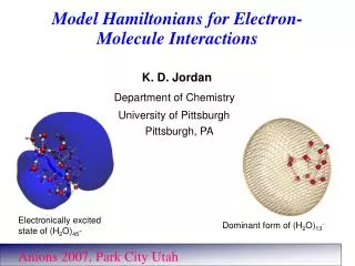
U. S. Department of Energy National Energy Technology Laboratory May 30, 2008 Electron interactions with CO2 Bob Merlino Department of Physics and Astronomy The University of Iowa Iowa City, IA
Electron attachment to CO2 • CO2 cannot permanently • bind an electron, so that • is metastable, with • lifetimes in the microsec to • millisec range, decaying • back to CO2 by auto- • detachment: • the electron attachmentprobability is enhanced if CO2is in an excited vibrational state attach. cross section (10-18 cm2) electron energy (eV) Y. Itikawa, J. Phys. Chem. Ref. Data, 31,749, 2002
Devices at the University of Iowa Plasma Laboratory • 2 Q machines with magnetic fields up to 0.5 T • 6 cm diam. by 2 m length, variable B profile • 6 cm diam. by 1 m length, which can also operate in the presence of micron sized dust particles • A glow discharge, dusty plasma / multidipole device, 60 cm diam. x 90 cm length • A multidipole/inductively coupled plasma device, 84 cm diam. x 130 cm length (The UI physics dept.has agreed to provide this device.)
Solenoid coils Gas inlet Cold Plate Plasma B Hot Plate hot filament Langmuir Probe K oven Hvac Pump Q machine / Discharge plasma • This device can be operated either with a thermal, surface ionizationplasma source (QM) which produces either as K or Cs plasma, or asa discharge device using He, Ar, Ne, Xe, N2, by removing the hot plate and biasing the filament negatively. • In the Q mode the electrons are relatively cold with Te ~ 0.2 eV • In the discharge mode there are thermal electrons with Te ~ 2 – 5 eV and with a population of energetic electrons with Ee ~ 30 –100 V.
IOWA Q-2 IOWA Q-3
130 cm MAGNETS LANGMUIR PROBE 84 cm FILAMENT Te 2 – 5 eV TURBOMOLECULAR PUMP Hot filament multidipole plasma source GAS
130 cm 84 cm LANGMUIR PROBE GAS Te 2 – 5 eV Inductively coupled plasma source TURBOMOLECULAR PUMP
K+ B = 0.3 T P(CO2) = 610–5 Torr Vprobe = 15 V 10 dB 0 100 200 300 400 500 Frequency (kHz) Formation of • The presence of • is confirmed by observing • the spectrum of ion cyclotron waves in the plasma • is a metastable negative ion
K+ Cs+ SF-6 -160 -120 -80 -40 0 40 80 120 160 Mass spectrometer measurements 2 ion plasma K+ / Cs+ K+/ SF6– plasma VOLTS