Download
1 / 4
40 likes | 153 Views
In this study, the exoskeleton arm has been analyzed to obtain the maximum sustainable load which is to be lifted by the arm hook. This preliminary analysis is required to design the capacity of another power source that operates the exoskeleton arm. For less power consumption and the weight, suitable material is selected. The 3 D model of the exoskeleton arm is prepared by using PROE software and computationally analyzed by using ANSYS transient structural tool. The results are simulated for different hook load condition. The safe design condition of the exoskeleton arm has been determined from the simulated results and the proposed model has been selected for the further advancements. H. A. Bhimgade | Utkarsh S. Dharamthok | Aryan S. Gajwe | Swastik Thawali | Ankush Kumbalwar "Design and Analysis of an Exoskeleton Arm" Published in International Journal of Trend in Scientific Research and Development (ijtsrd), ISSN: 2456-6470, Volume-4 | Issue-4 , June 2020, URL: https://www.ijtsrd.com/papers/ijtsrd30962.pdf Paper Url :https://www.ijtsrd.com/engineering/mechanical-engineering/30962/design-and-analysis-of-an-exoskeleton-arm/h-a-bhimgade<br>

E N D
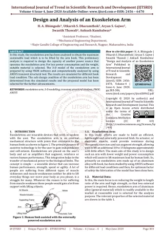
International Journal of Trend in Scientific Research and Development (IJTSRD) Volume 4 Issue 4, June 2020 Available Online: www.ijtsrd.com e-ISSN: 2456 – 6470 Design and Analysis of an Exoskeleton Arm H. A. Bhimgade1, Utkarsh S. Dharamthok2, Aryan S. Gajwe2, Swastik Thawali2, Ankush Kumbalwar2 1Assistant Professor, 2Student, 1,2Mechanical Engineering Department, 1,2Rajiv Gandhi College of Engineering and Research, Nagpur, Maharashtra, India ABSTRACT In this study, the exoskeleton arm has been analyzed to obtain the maximum sustainable load which is to be lifted by the arm hook. This preliminary analysis is required to design the capacity of another power source that operates the exoskeleton arm. For less power consumption and the weight, suitable material is selected. The 3-D model of the exoskeleton arm is prepared by using PROE software and computationally analyzed by using ANSYS transient structural tool. The results are simulated for different hook load condition. The safe design condition of the exoskeleton arm has been determined from the simulated results and the proposed model has been selected for the further advancements. KEYWORDS: exoskeleton arm; 3-D modelling; transient structural analysis; PROE; ANSYS How to cite this paper: H. A. Bhimgade | Utkarsh S. Dharamthok | Aryan S. Gajwe | Swastik Thawali | Ankush Kumbalwar "Design and Analysis of an Exoskeleton Arm" Published in International Journal of Trend in Scientific Research and Development (ijtsrd), ISSN: 2456- 6470, Volume-4 | Issue-4, June 2020, pp.303-306, www.ijtsrd.com/papers/ijtsrd30962.pdf Copyright © 2020 by author(s) and International Journal of Trend in Scientific Research and Development Journal. This is an Open Access article distributed under the terms of the Creative Commons Attribution License (CC (http://creativecommons.org/licenses/by /4.0) 1.1.Exoskeleton Arm: In this study, efforts are made to build an efficient, lightweight and externally powered limb. Its actuator, or electronic muscle, could provide resistance during therapeutic exercises and can augment strength, allowing user to lift an additional 10 to 15 kilograms approximately with little effort. The main aim of this study is to design such an arm with lower weight and power consumption which will assist to lift maximum load by human limb. So, primarily an exoskeleton arm made up of an aluminum alloy with hook, has been studied by using ANSYS software for different load conditions and then, for optimum factor of safety the fabrication of the model has been done here. 1.2.Material Data: In this, the main focus is on reducing the weight to length ratio of the arm and high strength, so that less external power is required. Hence, exoskeleton arm of aluminum alloy (general material) which is readily available in the market at reasonable cost is selected for the analysis purpose. The relevant properties of the selected material are shown in the table 1. IJTSRD30962 URL: BY 4.0) 1.INTRODUCTION Exoskeletons are wearable devices that work in tandem with the user. The exoskeleton arm is an external mechanical structure with joints that correlates to the human limbs as shown in figure 1. The primary purpose of assistive technology is for the user to gain independence and self-esteem. Exoskeletons are placed on the user's body and act as amplifiers that augment, reinforce or restore human performance. This integration helps in the transfer of mechanical power to the biological limbs. The concept is simple – a wearable device that can increase human performance, strength, speed or agility. A lot of people are suffering from different types of muscle sicknesses and muscle weaknesses neither be able to lift everyday things nor move your body as you please, is a struggle for many. Whatever the reason is for suffering from muscle weakness those people would gain a lot from support with lifting objects. Figure 1: Human limb assisted with the externally powered exoskeleton arm @ IJTSRD | Unique Paper ID – IJTSRD30962 | Volume – 4 | Issue – 4 | May-June 2020 Page 303
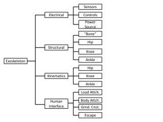
International Journal of Trend in Scientific Research and Development (IJTSRD) @ www.ijtsrd.com eISSN: 2456-6470 Table 1: Aluminum Alloy Properties Value Properties Tensile Ultimate Strength, MPa Value Density, kg mm^-3 2.77e-006 310 Coefficient of Thermal Expansion, C^- 1 Specific Heat, mJ kg^-1 C^-1 Compressive Yield Strength, MPa Tensile Yield Strength, MPa Young's Modulus, MPa 2.3e-005 71000 Poisson's Ratio 8.75e+005 0.33 Bulk 280 69608 Modulus, MPa Shear Figure 3: 3-D model of the exoskeleton arm 2.3.Finite Element Analysis: Transient dynamic analysis (sometimes called time-history analysis) is a technique used to determine the dynamic response of a structure under the action of any general time- dependent loads. This type of analysis is used to determine the time-varying displacements, strains, stresses, and forces in a structure as it responds to any combination of static, transient, and harmonic loads. The basic equation of motion solved by a transient dynamic analysis is: [M]{Ẍ} + [C]{Ẋ} + [K]{X} = F(t) Where, [M] = mass matrix; [C] = damping matrix; [K] = stiffness matrix; {Ẍ} = nodal acceleration vector; {Ẋ}= nodal velocity vector; {X} = nodal displacement vector; {F(t)} = load vector. At any given time, t, these equations can be thought of as a set of "static “equilibrium equations that also take into account inertia forces ([M]) and damping forces ([C]). The PROE model is analyzed for different hook load conditions using ANSYS v18.0 transient structural analysis for 1 second with proper boundary conditions. The arm upper elbow is kept fixed and constant force of 100 N is applied in upward direction at arm lower elbow which is rotating part of the arm. The table 2 shows the adopted meshing methodology used in the computational analysis. Table 2: Mesh Statistics Object Name State Display Display Style Defaults Physics Preference Solver Preference Relevance Element Midside Nodes Sizing Size Function Relevance Center Element Size Initial Size Seed Transition Span Angle Center Automatic Mesh Based Defeaturing Defeature Size Minimum Edge Length 280 26692 Modulus, MPa 2.Design Methodology: The selection of design methodology is a crucial part of any product development which may include many sequential steps that result in a fully functional design. In this study, a computational method has been adopted which is reliable and less expensive than the other conventional methods. The suitable computational model has been generated and analyzed with different load conditions. At the end, the suitable required design model of the exoskeleton arm has been selected here. 2.1.Methodology: The process of carrying out the study is depicted in the figure 1 The design and analysis methodology used in this study for the adoption of the best suitable design of exoskeleton arm. Mesh Solved Body Color Mechanical Mechanical APDL 0 Program Controlled Adaptive Medium 3.0 mm Active Assembly Fast Coarse Figure 2: Design Methodology 2.2.Exoskeleton arm design: The exoskeleton arm has been modelled using PROE modeling software with the material thickness of 5 mm, total mass of 0.79085 kg and total volume of 2.8552e+005 mm³. This model is shown in figure 2 and 3 respectively. On Default 7.2608e-003 mm @ IJTSRD | Unique Paper ID – IJTSRD30962 | Volume – 4 | Issue – 4 | May-June 2020 Page 304
International Journal of Trend in Scientific Research and Development (IJTSRD) @ www.ijtsrd.com eISSN: 2456-6470 Quality Check Mesh Quality Error Limits Target Quality Smoothing Mesh Metric Yes, Errors Standard Mechanical Default (0.050000) Medium None Inflation Use Automatic Inflation Inflation Option Transition Ratio Maximum Layers Growth Rate Inflation Algorithm View Advanced Options None Smooth Transition 0.272 5 1.2 Pre No Figure 5: Equivalent (Von-Mises) Strain Advanced Number of CPUs for Parallel Part Meshing Straight Sided Elements Number of Retries Program Controlled No Default (4) Dimensionally Reduced Disabled Program Controlled No Please Define No Rigid Body Behavior Mesh Morphing Triangle Surface Mesher Topology Checking Pinch Tolerance Generate Pinch on Refresh Statistics Figure 6: Equivalent (Von-Mises) Stress Nodes Elements 71286 31419 2.3.1.Exoskeleton Arm Hook Analysis: The gradual load on the hook is applied and increased from 10 N to 90 N. It is observed that at 90 N, minimum factor of safety (FOS) for the designed model is found out to be 0.84841. So, beyond this value analysis is stopped and for the fabrication purpose minimum FOS is considered at load of 80 N. Following graphs show the FOS, equivalent maximum stress, equivalent maximum strain and total deformation of the hook against different loading conditions. Figure 7: Factor of Safety Figure 8: Total Deformation with Load of 80 N Figure 4: Total Deformation @ IJTSRD | Unique Paper ID – IJTSRD30962 | Volume – 4 | Issue – 4 | May-June 2020 Page 305
International Journal of Trend in Scientific Research and Development (IJTSRD) @ www.ijtsrd.com eISSN: 2456-6470 safety. Thus, it has been observed that at load of 80 N, the results are optimum where minimum factor of safety is found out equivalent to 1. Hence, it can be concluded that the exoskeleton arm design is safe for the maximum hook load of 80 N or 8.15 kg approximately. It is safe to design other external power source for the required load condition so that it will operate the exoskeleton arm which may handle or bear approximately 80 percentage of total load for lifting any object which ultimately helps to minimize or reduce the human limb stresses. The design and analysis of the exoskeleton arm helps to identify the strong and weak parts of the design and hence suitable modification is to be done before final fabrication. Further, in future, the whole body of the exoskeleton arm can be more realistically optimized using suitable transient dynamic structural models with appropriate boundary conditions. REFERENCES [1]Zhibin Song, Shuxiang Guo, “Development of a New Compliant Exoskeleton Device for Elbow Joint Rehabilitation." Proceedings of the 2011 IEEE/ICME International Conference on Complex Medical Engineering, pp.647-651, 2011. Figure 9: (Von-Mises) Strain with Load of 80 N Figure 10: (Von-Mises) Stress with Load of 80 N [2]Shuxiang Guo, Songyuan Zhang, Muye pang and Yuta Nakatsuka, "Preliminary Study on Upper Limb Movement Identification Based on sEMG signal." Proceedings of the2012 ICME International Conference on Complex Medical Engineering, pp.683-688, 2012. [3]ShuxiangGuo, FanZhang, WeiWei, “Development of Force Analysis-based Exoskeleton for the Upper Limb Rehabilitation System,” Proceedings of 2013 ICME International Conference on Complex Medical Engineering May 25-28, Beijing, China [4]LiaiPan, ChunshanHe, QinghuaLi, “StructuralStatic Characteristic Analysis of Lower Limb Exoskeleton BasedonFiniteElementModeling,”ICMEIS2015. Figure 11: FOS with Load of 80 N Conclusion The exoskeleton arm has been analyzed using transient structural analysis for different load conditions at the hook keeping the upper elbow of an arm fixed. The analysis is carried out in ANSYS v18.0 software for the time period of 1 second. The load is increased from 10 N to 90 N and the results are obtained for each condition for body deformation or displacement, stress- strain (Von-Mises) and the factor of [5]J. C. Perry, J. Rosenand S. Burns, "Upper-Limb Powered Exoskeleton Design," in IEEE/ASME Transactions on Mechatronics, vol.12, no.4, pp.408-417, Aug.2007, doi: 10.1109/TMECH. 2007. 901934. [6]“TransientStructuralAnalysis,”ANSYSv18.0manual. @ IJTSRD | Unique Paper ID – IJTSRD30962 | Volume – 4 | Issue – 4 | May-June 2020 Page 306