Download
1 / 7
80 likes | 103 Views
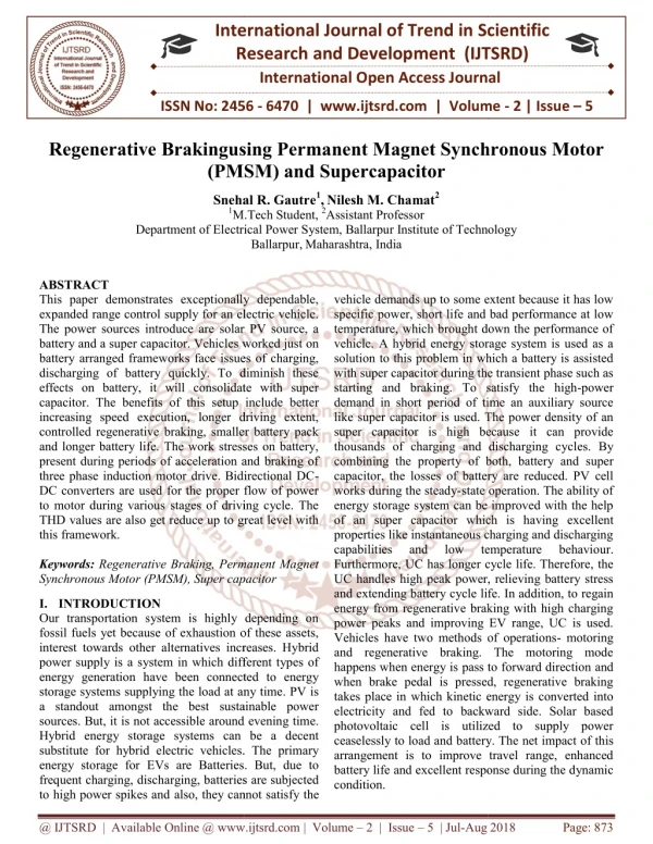
The purpose of this project is to design an Electrical vehicle with help renewable energy source which can carry the lab equipment, books and other goods from one building to other building of AL FALAH UNIVERSITY also student as well as professors can go easily from one building to other building of AL FALAH UNIVERSITY. This paper gives a review of the electric vehicle technology that focuses on the types of drives and the control of speed of five phase permanent magnet synchronous motor. This paper highlights the characteristics, performance measure, requirements and the operational procedure of the electric vehicle drives and control. Dhirender Kumar | Ameen Uddin Ahmad "Design an electric vehicle using PV array with five-phase permanent magnet synchronous motor." Published in International Journal of Trend in Scientific Research and Development (ijtsrd), ISSN: 2456-6470, Volume-3 | Issue-6 , October 2019, URL: https://www.ijtsrd.com/papers/ijtsrd29173.pdf Paper URL: https://www.ijtsrd.com/engineering/electrical-engineering/29173/design-an-electric-vehicle-using-pv-array-with-five-phase-permanent-magnet-synchronous-motor/dhirender-kumar<br>

E N D
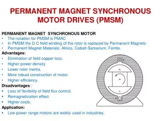
International Journal of Trend in Scientific Research and Development (IJTSRD) Volume 3 Issue 6, October 2019 Available Online: www.ijtsrd.com e-ISSN: 2456 – 6470 Design an Electric Vehicle using PV Array with Five-Phase Permanent Magnet Synchronous Motor Dhirender Kumar, Ameen Uddin Ahmad Department of Electrical and Electronics Engineering, Al-Falah University, Faridabad, Haryana, India ABSTRACT The purpose of this project is to design an Electrical vehicle with help renewable energy source which can carry the lab equipment, books and other goods from one building to other building of AL-FALAH UNIVERSITY also student as well as professors can go easily from one building to other building of AL-FALAH UNIVERSITY. This paper gives a review of the electric vehicle technology that focuses on the types of drives and the control of speed of five- phase permanent magnet synchronous motor. This paper highlights the characteristics, performance measure, requirements and the operational procedure of the electric vehicle drives and control. KEYWORDS: PV array, Boost converter, MPPT, Three phase inverter, five-phase permanent magnet synchronous moto, MATLAB How to cite this paper: Dhirender Kumar | Ameen Uddin Ahmad "Design an Electric Vehicle using PV Array with Five-Phase Permanent Magnet Synchronous Motor" Published in International Journal of Trend in Scientific Research and Development (ijtsrd), ISSN: 2456-6470, Volume-3 | Issue-6, October 2019, https://www.ijtsrd.com/papers/ijtsrd2917 3.pdf Copyright © 2019 by author(s) and International Journal of Trend in Scientific Research and Development Journal. This is an Open Access article distributed under the terms of the Creative Commons Attribution License (CC (http://creativecommons.org/licenses/by/ 4.0) IJTSRD29173 pp.561-565, URL: BY 4.0) I. Photo-voltaic (PV) cells are used for the generation of direct current (DC) voltage and can be supplied to buck converter, enhance converter etc. A solar panel is made up of six different components, but arguably the most important one is the photovoltaic cell, which actually generates electricity. The conversion of sunlight into electrical energy by a solar cell is called the “photovoltaic effect. Solar PV cells generate electricity by absorbing sunlight and using that light energy to create an electrical current. There are many photovoltaic cells within a single solar panel, and the current created by all of the cells together adds up to enough electricity to help power your home. A standard panel used in a rooftop residential system will have 60 cells linked together. Commercial solar installations often use larger panels with 72 or more photovoltaic cells.The most widely used cells are polycrystal silicon cells (54.5% of the world’s market share) and single crystal silicon cells (29.36% of the world’s market share). Normally, the electric characteristics of a PV cell are displayed as a relation between the cell voltage and current, and a relation between the cell voltage and power. Accordingly, several electric quantities that are important to the operation of the PV system are identified. These electric quantities include: the cell voltage under open circuit conditions, VOC, the cell current under short circuit conditions, ISC, and the cell voltage, current and power at the maximum power point, VMPP, IMPP, and, PMPP, respectively[1]. Figure-1 display the electric characteristics of a common PV cell. The out put voltage of PV array will INTRODUCTION increase by stepup chopper then a 3 phase inverter invert the that dc supply and by that inverted output five-phase permanent magnet synchronous motor will excite. We are controlling duty cycle of chopper with the help of MPPT. Maximum power point tracking (MPPT)or sometimes just power point tracking (PPT) is a technique used commonly with wind turbines and photovoltaic (PV) solar systems to maximize power extraction under all conditions. Although it primarily applies to solar power, the principle applies generally to sources with variable power: for example, optical and thermophotovoltaics[2]. PV solar systems exist in many different configurations with regard to their relationship to inverter systems, external grids, battery banks, or other electrical loads. Regardless of the ultimate destination of the solar power, though, the central problem addressed by MPPT is that the efficiency of power transfer from the solar cell depends on both the amount of sunlight falling on the solar panels and the electrical characteristics of the load. As the amount of sunlight varies, the load characteristic that gives the highest power transfer efficiency changes, so that the efficiency of the system is optimized when the load characteristic changes to keep the power transfer at highest efficiency. This load characteristic is called the maximum power point (MPP) and MPPT is the process of finding this point and keeping the load characteristic there. Electrical circuits can be designed power transmission @ IJTSRD | Unique Paper ID – IJTSRD29173 | Volume – 3 | Issue – 6 | September - October 2019 Page 581
International Journal of Trend in Scientific Research and Development (IJTSRD) @ www.ijtsrd.com eISSN: 2456-6470 to present arbitrary loads to the photovoltaic cells and then convert the voltage, current, or frequency to suit other devices or systems, and MPPT solves the problem of choosing the best load to be presented to the cells in order to get the most usable power out[3]. Characteristics of a Solar Cell Maximum power point tracking of the solar PV array (a) Fig -1 II. METHODOLOGY A.OPERATING PRINCIPLE: Generated power from the PV array which is not sufficient for the rotation of induction motor, that’s why we have to increase the level of DC voltage by using stepup chopper and then we will convert the the DC supply to three phase AC supply that conversion is possible by using three phase Bridge type inverter it can be 180 mod are 120 mod with pwm Technology that generated 3 phase supply will be input of 3 phase induction motor[4]. Output of chopper which is depend on duty cycle can be controlled by MPPT, MPPT is a device which generate a signal that signal will control the duty cycle of chopper explained in fig-2. (b) Fig-2 Block diagram of electric vehicle Fig-3 Three phase induction motor driven by PV array with MPPT Chopper based system for electric vehicle @ IJTSRD | Unique Paper ID – IJTSRD29173 | Volume – 3 | Issue – 6 | September - October 2019 Page 582
International Journal of Trend in Scientific Research and Development (IJTSRD) @ www.ijtsrd.com eISSN: 2456-6470 III. (a)-Three phase full bridge inverter: Fig-4Three phase full bridge inverter The three-phase dc to ac voltage source inverters are extensively being used in motor drives, active filters and unified power flow controllers in power systems and uninterrupted power supplies to generate controllable frequency and ac voltage magnitudes using various pulse width modulation (PWM) strategies[5]. The standard three-phase inverter shown in Figure 4 has six switches the switching of which depends on the modulation scheme[6]. As in the single phase voltage source inverters PWM technique can be used in three-phase inverters, in which three sine waves phase shifted by 120°with the frequency of the desired output voltage is compared with a very high frequency carrier triangle, the two signals are mixed in a comparator whose output is high when the sine wave is greater than the triangle and the comparator output is low when the sine wave or typically called the modulation signal is smaller than the triangle. This phenomenon is shown in Figure- 5 As is explained the output voltage from the inverter is not smooth but is a discrete waveform and so it is more likely than the output wave consists of harmonics, which are not usually desirable since they deteriorate the performance of the load, to which these voltages are applied[7]. Fig-5 PWM illustration by the sine-triangle comparison method (a) sine triangle comparison (b) switching pulses IV. The line-line output voltages waveforms would consist of harmonics orders 1, 3, 5, 7, 9, … and so on. Because of phase 120 degree shift between the waveforms, the triplen (of order which are multiples of 3) of both will of the same phase and hence these cancel in the process of subtraction. Consequently, the triplen order harmonic voltages are eliminated from the line – line voltage. The remaining harmonics are at n = 6r ± 1 where r is any positive integer, the n th harmonic having an amplitude 1/n times the fundamental component[8]. (b) Output voltage of inverter: @ IJTSRD | Unique Paper ID – IJTSRD29173 | Volume – 3 | Issue – 6 | September - October 2019 Page 583
International Journal of Trend in Scientific Research and Development (IJTSRD) @ www.ijtsrd.com eISSN: 2456-6470 (1) The RMS values of the fundamental and higher order output voltages are (2) V. A boost converter is one of the simplest types of switch mode converter. As the name suggests, it takes an input voltage and boosts or increases it. All it consists of is an inductor, a semiconductor switch (these days it’s a MOSFET, since you can get really nice ones these days), a diode and a capacitor. Also needed is a source of a periodic square wave. This can be something as simple as a 555 timer or even a dedicated SMPS IC like the famous MC34063A IC[9]. Boost converter: Fig-6 Boost converter Vs is input voltage and V0 is output voltage of converter Fig-7 Input and output voltage and current of boost converter Out put voltage of stepup chopper V= (3) @ IJTSRD | Unique Paper ID – IJTSRD29173 | Volume – 3 | Issue – 6 | September - October 2019 Page 584
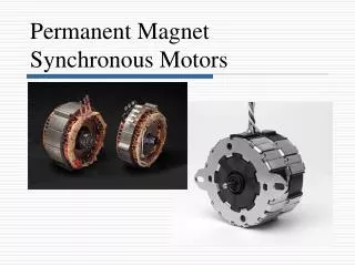
International Journal of Trend in Scientific Research and Development (IJTSRD) @ www.ijtsrd.com eISSN: 2456-6470 Fig-8 Model of solar cell with boost converter and MPPT system Above fig shows block diagram PV cell with MPPT where output of pv cell goes to MPPT and also to boost converter , MPPPT generate a signal by comparing with a reference signal and that generated signal goes to IGBT (for triggering ) by changing the pulse duration of pulls signal we can change the duty cycle and output of boost converter. As we know output voltage of boost converter will has been explained in boost converter[10]. VI. Permanent magnet synchronous motors (PMSMs) are similar to ordinary synchronous motors, with the exception that their field winding has been replaced with a permanent magnet. Among these motors, five-phase PMSM has a number of features such as higher efficiency, reliability, and power density than other types of PMSM . These motors are commonly used in special industrial cases such as marine propulsion systems, hybrid vehicles, and the aerospace industry. In most cases, it is necessary to design a proper driver with small size and high reliability[11] . One of the common methods to control the torque (and thus finally the speed) of these motor is Direct Torque Control (DTC). VII. Results and discussion: With the combination of the carefully designed torque, speed and direction control circuit, it can form a better motor driver for PV array system. This motor driver circuit is builded based on the idea to control the cost as low as possible. Therefore, the list of components used is simple and easy to be found in the market. Although the cost is low, the resultant driver delivers excellent capability of controling the speed and torque in a linear manner. The driver managed to control the current and the voltage of the output at the same time and therefore it can controls the resultant power transfer to the motor. The motor is only consumes maximum of 15 A. When it work on full load. This stable and easy control definitely will shorten the development period for engineers to design the solar system Five-Phase Permanent Magnet Synchronous Motors: . Fig- 9 Motor outputs @ IJTSRD | Unique Paper ID – IJTSRD29173 | Volume – 3 | Issue – 6 | September - October 2019 Page 585
International Journal of Trend in Scientific Research and Development (IJTSRD) @ www.ijtsrd.com eISSN: 2456-6470 Fig-10 PV inputs Fig-11 PV output power Fig-12 Rotor voltage and current @ IJTSRD | Unique Paper ID – IJTSRD29173 | Volume – 3 | Issue – 6 | September - October 2019 Page 586
International Journal of Trend in Scientific Research and Development (IJTSRD) @ www.ijtsrd.com eISSN: 2456-6470 References. [1]“Photovoltaic Cell Conversion Efficiency,” U.S. Department of Energy, Retrieved, 19 May 2012. Controller,” Electronics, vol/issue: 50(4), pp. 749- 758, 2003. IEEE Transactions on Industrial [7]P. H. Zope, et al, “Performance and Simulation Analysis of Single-Phase Grid Connected PV System Based on ZSource Inverter,” in International conference on Power Electronics, Drives and Energy System, 2010. [2]D. Sera, et al., “On the Perturb-and-Observe and Incremental Conductance MPPT Methods for PV Systems,” IEEE Journal of Photovoltaics, vol/issue: 3(3), pp. 1070-1078, 2013. [8]S. Li, et al, “A Novel Maximum Power Point Tracking Control MethodWithVariable Weather Parameters for Photovoltaic Systems,” (ELSEVIER), Solar Energy, vol. 97, pp. 529-536, 2013. [3]F. Liu, et al., “Variable Step Size INC MPPT Method for PV Sytems,” IEEE Transactions. [4]Muhammad Arrofiq & Nordin Saad “ Control of Induction Motor Drives Using Modified-Fuzzy Logic Methods” IEEE 2010 pp 612-619. Industrial Electronics, vol/issue: 55(7), 2008. [9]Celik, experimental verification of the operating current of mono –crystalline photovoltaic modules using four – and five parameter models.Applied Energy. 84: 1 – 15. A.N. Acikgoz, N.2007. Modelling and [5]T. F. Wu, et al., “A Fuzzy Logic-Controlled Single Stage Converter for PV-Powred Applications,” IEEE Transactions on Industrial Electronics, vol/issue: 47(2), pp. 287–296, 2000. Lighting System [10]S. Chin, J. Gadson, and K. Nordstrom. Maximum power point tracker.Tufts University Department of Electrical Engineering and Computer Science, 2003, pp.1 – 66. [6]M. Veerachary, et al., “Neural-Network Based Maximum Power Point Tracking of CoupledIductor Interleaved- Boot Converter Supplied PV System Using Fuzzy [11]P. Zhao and G. Yang, “Torque Density Improvement of Five-Phase PMSM Drive for Electric Vehicles Applications.” @ IJTSRD | Unique Paper ID – IJTSRD29173 | Volume – 3 | Issue – 6 | September - October 2019 Page 587