Download
1 / 8
80 likes | 261 Views
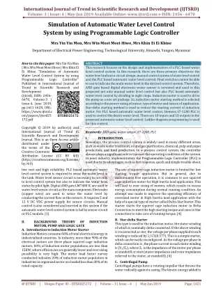
This research focuses on the design and implementation of a PLC based water level control system. In this research, there are three primary objectives the water level indicator circuit design, manual control system of water level control and the PLC based automatic water level control. Float switches cannot be able to use to indicate the multi water level in the desired control system. Therefore, AND gate based digital electronic water sensor is invented and used in this proposed not only manual water level control but also PLC based automatic water level control by dividing in eight steps. Induction motor is used to drive the pump as a one set package. So, induction motor starting method is selected according to the power rating of motor, type of motor and nature of application. Star delta starting method is used to reduce the starting current of induction motor. For PLC based automatic water level control, Siemens S7 1200 PLC is used to control the desire water level. There are 10 inputs and 10 outputs in the proposed automatic water level control. Ladder diagram programming is used for this control. Mrs Yin Yin Mon | Mrs Win Moet Moet Htwe | Mrs Khin Ei Ei Khine "Simulation of Automatic Water Level Control System by using Programmable Logic Controller" Published in International Journal of Trend in Scientific Research and Development (ijtsrd), ISSN: 2456-6470, Volume-3 | Issue-4 , June 2019, URL: https://www.ijtsrd.com/papers/ijtsrd25172.pdf Paper URL: https://www.ijtsrd.com/engineering/electrical-engineering/25172/simulation-of-automatic-water-level-control-system-by-using-programmable-logic-controller/mrs-yin-yin-mon<br>

E N D
International Journal of Trend in Scientific Research and Development (IJTSRD) Volume: 3 | Issue: 4 | May-Jun 2019 Available Online: www.ijtsrd.com e-ISSN: 2456 - 6470 Simulation of Automatic Water Level Control System by using Programmable Logic Controller Mrs Yin Yin Mon, Mrs Win Moet Moet Htwe, Mrs Khin Ei Ei Khine Department of Electrical Power Engineering, Technological University, Hmawbi, Yangon, Myanmar How to cite this paper: Mrs Yin Yin Mon | Mrs Win Moet Moet Htwe | Mrs Khin Ei Ei Khine "Simulation of Automatic Water Level Control System by using Programmable Logic Published in International Journal of Trend in Scientific Research and Development (ijtsrd), ISSN: 2456- 6470, Volume-3 | Issue-4, June 2019, pp.1621-1628, URL: https://www.ijtsrd.c om/papers/ijtsrd25 172.pdf Copyright © 2019 by author(s) and International Journal of Trend in Scientific Research and Development Journal. This is an Open Access article distributed under the terms of the Creative Commons Attribution License (CC BY 4.0) (http://creativecommons.org/licenses/ by/4.0) low cost and high reliability. PLC based automatic water level control system is required to sense the water level in the tank. Water level sensor circuit is necessary in not only to level control system but also to indicate the water level status by pilot light. Digital AND gate LM7408 IC are used in water level sensor circuit as the main component. Electrodes (copper wire) are used to sense the water level by conducting the current flow as the sensors. It requires 5 and 12 V DC VDC power supply for sensor circuits. Manual control is also considered and inserted in this system if the automatic water level control system is fail by sensor circuit or PLC module. [1] II. BACKGROUND THEORY MOTOR, PUMP AND LOGIC GATE A.Introduction to Induction Motor Starter Induction Motors consume 60% of total electrical energy in industrialized countries. In industry, more than 90% of the electrical motors are three phase squirrel-cage induction motors. 80% of Induction motor populations are less than 15KW, where efficiencies are generally lower and over sizing possibility is very high. The motor load factor survey conducted indicates 20% of induction motor population in industries in organized sector are loaded less than 30% of its rated capacity. ABSTRACT This research focuses on the design and implementation of a PLC-based water level control system. In this research, there are three primary objectives: the water level indicator circuit design, manual control system of water level control and the PLC based automatic water level control. Float switches cannot be able to use to indicate the multi water level in the desired control system. Therefore, AND gate based digital electronic water sensor is invented and used in this proposed not only manual water level control but also PLC based automatic water level control by dividing in eight steps. Induction motor is used to drive the pump as a one set package. So, induction motor starting method is selected according to the power rating of motor, type of motor and nature of application. Star-delta starting method is used to reduce the starting current of induction motor. For PLC based automatic water level control, Siemens S7-1200 PLC is used to control the desire water level. There are 10 inputs and 10 outputs in the proposed automatic water level control. Ladder diagram programming is used for this control. Keywords: AND gate, water sensor, S7-1200, PLC I. INTRODUCTION Nowadays, the process control system is widely used in many different areas, such as waste water treatment, oil and gas purification, chemical, pulp and paper production, and food production. In a process control system, the controller always plays a significant role to transact the operating conditions of the system. In most industry implementation, the Programmable Logic Controller (PLC) is used due to its advantages, such as fast response, quick and simple trouble-shoot, The use of squirrel cage induction motor is limited for low starting torque application. But in general, due to maintenance free operation, it is common to use squirrel cage induction motor for High Inertia load application. This will lead to over sizing of motors, which results in excess energy consumption during normal running condition. An attempt was made to improve the operating efficiency of oversized motor in High Inertia load application with the help of a special type of starter called Delta-Star Starter. This starter starts the squirrel cage induction motor in Delta Connection to meet the high starting torque and runs in Star connection to take care of running torque. [4] B.Star-delta Starter This type is used for the induction motor, the stator winding of which is nominally delta-connected. If the above winding is reconnected as star, the voltage per phase supplied to each winding is reduced by 1/√3(0.577). This is a simple starter, which can be easily reconfigured. As the voltage per phase in delta connection is , the phase current in each stator winding is (Vs/Zs), where Zs is the impedance of the motor per phase at standstill or start (stator impedance and rotor impedance referred to the stator, at standstill). [4] C.Centrifugal Pump Centrifugal pumps have a rotating impeller that throws the water radically against a casing. The kinetic energy added to Controller" IJTSRD25172 OF INDUCTION @ IJTSRD | Unique Paper ID – IJTSRD25172 | Volume – 3 | Issue – 4 | May-Jun 2019 Page: 1621
International Journal of Trend in Scientific Research and Development (IJTSRD) @ www.ijtsrd.com eISSN: 2456-6470 the water by the impeller is then converted to potential energy in the form of pressure or ‘head’ in the diffuser or volute section. As the water exits the pump through the diffuser, the cross-section increases, causing the velocity (kinetic energy) to reduce and, by conservation of energy, the potential energy is increase. For conventional centrifugal pump designs, high efficiencies are only obtained for low pumping pressures and hence relatively small pumping heads of less than about 25 m. Other advantages of centrifugal pumps include their simplicity (with a minimum of moving parts) and corresponding reliability, low cost, robustness, tolerance to pumping particulates and low starting torque. On the other hand, another potential limitation of centrifugal pumps is their inability to be self- priming, although technology exists for overcoming this impediment. Consequently, they are frequently used as submersible pumps, preferably in conjunction with a submersible motor. For many years this has been a problem, since the preferred DC motors were not submersible owing to the presence of the brushes. High efficiency can be obtained with small clearances and narrow passages, but this is undesirable for pump reliability and the ability to pump liquids contaminated with particles. In addition, high efficiency can be obtained with a high speed impeller, which again acts to shorten the life of the pump. In summary, pumps need to be designed and selected for specific applications and environments. [4] (b) (a) (c) (d) (e) (f) (g) Figure2. various type of gate IC, (a) 7408 Quad 2 input AND Gates, (b) 7432 Quad 2 input OR Gates, (c) 7400 Quad 2 input NAND Gates, (d) 7402 Quad 2 input NOR Gates, (e) 74266 Quad 2 input XNOR Gates, (f) 7404 Hex NOT (Gates Inverters), (g) 74133 Single 13 input NAND Gate. [3] III. BASIC KNOWLEDGE AND USEFUL FUNCTIONS OF S7-1200 A.Basic Requirements for PLC Control In order to create or change a program, the following items are needed: ?Programmable logic controller (PLC) ?Programming device ?Programming software ?Connector cable [2] i. Programmable Logic Controller (PLC) Throughout this research the S7-1200 PLC is used because of its ease of use. Figure1. Centrifugal Pump Operation [4] D.Logic Gates Figure 2, illustrates a selection of the basic gates logic gates that are available from a number of manufacturers in standard families of integrated circuits. Each logic family is designed so that gates and other logic ICs within that family (and other related families) can be easily combined, and built into larger logic circuits to carry out complex functions with the minimum of additional components. Typically, standard logic gates are available in14 pin or 16 pin DIL (dual in line) chips. The number of gates per IC varies depending on the number of inputs per gate. Two-input gates are common, but if only a single input is required, such as in the 7404 NOT (or inverter) gates, a 14 pin IC can accommodate 6 (or Hex) gates. The greatest number of inputs on a single gate is on the 74133 13 input NAND gate, which is accommodated in a 16 pin package. [3] Figure3. S7- 1200 PLC Unit [6] ii. The program is created in a programming device (PG) and then transferred to the PLC. The program for the S7-200 can be created using a dedicated Siemens SIMATIC S7 programming device. Programming Devices @ IJTSRD | Unique Paper ID – IJTSRD25172 | Volume – 3 | Issue – 4 | May-Jun 2019 Page: 1622
International Journal of Trend in Scientific Research and Development (IJTSRD) @ www.ijtsrd.com eISSN: 2456-6470 are required to control the pump motor. Completed circuit diagram of water level indicator and sensor control circuit is shown in figure 6. In the circuit diagram, the eight number of AND gates are used to get the sequential step control according to the nature of water level. LM7408 AND gate IC is used in this circuit for both indicators and sensors. Each LM7408 AND gate IC contains four AND gates as two input gate function. LM7408 AND gate IC operates with 5V DC supply. Relays are operating with 12VDC supply. So power supply is designed for both 5V DC and 12VDC fro, 220V AC. To get the desired DC voltage level of gate ICs, LM7805 voltage regulator IC is used to obtain the 5V DC constant. Relays are supplied by rectifier and filter output directly. Voltage regulator IC is not required for relay operation because relay can operate between 11 V DC to 15 V DC. 1000 μF 25V capacitor is used as a voltage filter to eliminate the ripple voltage and frequency of rectifier. 10 μF, 16V capacitor is used in the output of LM7805 IC to eliminate the noise voltage signal by surge voltage. C1384 NPN transistors are used in all relay driver circuit. 10k ohm resistors are used to ground the inputs of AND gates. 330 ohm resistors are used to limit the LED operating voltage. 10 ohm resistors are totally 16 numbers and 330 ohm resistors are totally 19 numbers in gate circuits. C1384 NPN transistors are totally 3 numbers and relays are also totally 3 numbers for the three control states. One blue LED is used to indicate the maximum level of water. Two green LEDs are used to indicate the minimum level of water. Three yellow LEDs are used to indicate the middle level of water. Two red LEDs are used to indicate the under limit level of water in the tank. Figure4. PG Programming Device for the S7-1200 PLC [6] iii. A software program is required in order to tell the PLC what instructions it must follow. Programming software is typically PLC specific. A software package for one PLC, or one family of PLCs, such as the S7 family, would not be useful on other PLCs. The S7-1200 uses a Windows based software program called STEP 7- Micro/WIN32. Micro/WIN32 is installed on a personal computer in a similar manner to any other computer software. [5] iv. Connector Cables PPI (Point-to-Point Interface) Connector cables are required to transfer data from the programming device to the PLC. Communication can only take place when the two devices speak the same language or protocol. Communication between a Siemens programming device and the S7-1200 is referred to as PPI protocol (point to- point interface). The S7-1200 uses a 9-pin, D-connector. This is a straight-through serial device that is compatible with Siemens programming devices (MPI port) and is a standard connector for other serial interfaces. [2] IV. DESIGN AND TESTING OF PROPOED WATER LEVEL CONTROL SYSTEM A.Introduction to Design Consideration In this section, design consideration of hardware and PLC ladder program of the water level control system is described. Firstly, hardware system is considered for both water level sensor circuit and PLC control. Water level control system can be divided in three sections such as A.Water level indicator and sensor control circuit B.Manual water level control system by relay C.Automatic water level control system by PLC Software Figure5. Prototype of automatic water level control system B.Water level indicator and sensor control circuit Water level indicator and sensor control circuit consists of eight steps to show the water level in the tank. There are three relay outputs to give the signal to PLC input such as (i) under limit level, (ii) minimum limit level and (iii) maximum limit level. The under limit level signal is required in the control to avoid the pumping without water in the underground tank. Maximum and minimum limit level signal Figure6. Completed circuit diagram of water level indicator and sensor control circuit @ IJTSRD | Unique Paper ID – IJTSRD25172 | Volume – 3 | Issue – 4 | May-Jun 2019 Page: 1623
International Journal of Trend in Scientific Research and Development (IJTSRD) @ www.ijtsrd.com eISSN: 2456-6470 C.Operation Of Water Level Indicator Control System The flow chart of water level indicator control circuit is shown in figure 7. The water in the tank is used as a conductor to act like sensors. So, the sensors are very simple and it can save the cost of control circuit. When there is no water in the tank, the under limit sensor is not actuate and sent a signal to the PLC input module. If the pump motor is running to supply the water in the tank, the water level will be rise slowly. If the level reach the under level limit, the sensor (S1) will actuate and send the signal to the relay as an ON state. Due to water level increment by pump motor running, it will reach to the next 2nd state. And then the sensor (S2) will actuate and red LED is light on. If the water level reach to the 3rd state level, the sensor (S3) will actuate and it may turn yellow LED is light on. If the water level reach to the 4th state level, the sensor (S4) will actuate and it may turn yellow LED is light on. Next, if the water level reach to the 5th state level, the sensor (S5) will actuate and it may turn yellow LED is light on. Yellow LEDs indicate the middle level of water in the tank. If the water level reach to the 6th state level, the sensor (S6) will actuate and it may turn green LED is light on. If the water level reach to the 7th state level, the sensor (S7) will actuate and it may turn green LED is light on. And also, relay outputs the contact to send a minimum water level signal to the PLC to run the pump motor. Green LEDs indicate the upper level of water in the tank. If the water level reach to the 8th state level, the sensor (S8) will actuate and it may turn blue LED is light on. At the same time, relay outputs the contact to send a maximum water level signal to the PLC to stop the pump motor. If the water level refill and under of the 7th state level, the pump motor restarts to run again to maintain the water level between the minimum and maximum level. D.Manual water level control system Manual control is used in water pumping system as an auxiliary control if the automatic system is fail to pump the water due to water level sensor fault. One of the power circuits of star-delta control is shown in figure 8. Over load in the power circuit tend to protect the motor winding if the over current occurs at the motor winding. Circuit breaker in the circuit tends to protect the power line if the faults occur at motor control. Figur8. Power Line diagram of water level control Manual control circuit is shown in figure 9. It consists of 6 magnetic contactors, 2 timer, 4 pilot light and 4 push buttons. Figure7. Flow chart of water level indicator control circuit Figure9. Manual Control Circuit of water level control @ IJTSRD | Unique Paper ID – IJTSRD25172 | Volume – 3 | Issue – 4 | May-Jun 2019 Page: 1624
International Journal of Trend in Scientific Research and Development (IJTSRD) @ www.ijtsrd.com eISSN: 2456-6470 E.Automatic water level control system by PLC Figure10. Flow chart of automatic water level control In this research, combination of gate electronic sensor circuit for water level indicator light and pump motor control by PLC is used to get perfect and more reliable control system. The control system of flow chart is shown in figure 10. Siemen S7-1200 PLC is used in control circuit associated with programming software. Ladder diagram language is used in program because it is the most familiar language and easy to visual operation in simulation by graphical symbols. Figure 11 shows the PLC ladder diagram of automatic water level control system. Figure 12 shows the connection diagram of input switch, sensor and output relays and pilot light. @ IJTSRD | Unique Paper ID – IJTSRD25172 | Volume – 3 | Issue – 4 | May-Jun 2019 Page: 1625
International Journal of Trend in Scientific Research and Development (IJTSRD) @ www.ijtsrd.com eISSN: 2456-6470 @ IJTSRD | Unique Paper ID – IJTSRD25172 | Volume – 3 | Issue – 4 | May-Jun 2019 Page: 1626
International Journal of Trend in Scientific Research and Development (IJTSRD) @ www.ijtsrd.com eISSN: 2456-6470 Figure11. PLC ladder diagram program of automatic water level control system Input List I0.0= system stop, I0.5 = GT min level limit switch I0.1= system start, I0.6 = GT max level limit switch I0.2= emergency stop, I0.7 = OH min level limit switch I0.3= fail safe switch, I1.0 = OH max level limit switch I0.4= quick start, I0.6 = GT under level limit switch Output List O0.0= System RUN PL, O0.5= GT Pump STOP PL O0.1= System STOP PL, O0.6= MMC2 O0.2= MMC1, O0.7= YMC2 O0.3= YMC1, O1.0= DMC2 O0.4= DMC1, OI0.6= OH Pump STOP PL Figure12. Connection diagram of input switch, sensor and output relays and pilot light @ IJTSRD | Unique Paper ID – IJTSRD25172 | Volume – 3 | Issue – 4 | May-Jun 2019 Page: 1627
International Journal of Trend in Scientific Research and Development (IJTSRD) @ www.ijtsrd.com eISSN: 2456-6470 V. This research investigates a designing process of PLC based automatic water level control system. In this system, Siemens S7-1200 PLC, Star-delta based induction motor starting control and AND gate IC based water level sensor circuits are used. In this research, eight steps of water level are considered as the sample water level indicators. If the more steps are required to indicate the water level according to the size of tanks, the AND gate IC can be added in the water level sensor circuits. PLC based water level control used in industrial water supply is the most reliable control and the best control for sequential process. ACKNOWLEDGEMENT The author would like to express her gratitude to Dr. Nay Soe Shwe, Professor and Head of Electrical Power Engineering Department, (Hmawbi) for his encouragement and helpful suggestion and supervision. The author wishes to thanks all my colleagues. Thanks are also extended to her dear parents and friends for their support. Conclusions REFERENCES [1]National 06th.07th.April 2016. Water Level Monitoring by Using PLC. Conference “Convergence 2016,” [2]Gebremaryam “Automatic Fluid Level Control Using Programmable Logic Controller”. Alem ,Dr.Krishnanaik Vankdoth, [3]Haoqiang Ji, “PLC Programming For A Water Level Control System: Implementation”,2017 Design and System [4]Kharagpur, “Different Types of Starters for Induction Motor (IM)”, 2011 [5]W. Bolton, “Programmable logic controllers”. Newnes, 2015. Technological University [6]Siemens AG, “One hour Primier”, Microsystems Siematic S7- 200, Federal Republic of Germany, (2008). @ IJTSRD | Unique Paper ID – IJTSRD25172 | Volume – 3 | Issue – 4 | May-Jun 2019 Page: 1628