Download
1 / 10
100 likes | 129 Views
In this work presents a scientific approach to optimizing Friction Stir welding method parameters for the aluminium alloy. Friction stir Welding FSW is wide used for the welding of Al alloy. Welding input parameters play a really vital role in decisive the standard of a weld joint. The welding parameters like tool shoulder diameter, tool motility speed, welding speed and axial force play a serious role when deciding the joint strength. In gift study an endeavour are created to affix the AA6061 Al alloy by mistreatment the traditional shaper. Non consumable tool, manufactured from high carbon, high chromium steel alloys steel, H13 are wont to fabricate the joints. Friction stir welding are dispensed on the 6 mm thick AA6061 plate. Three factors are wont to minimize range of experimental conditions. Total eighteen experiments are dispensed. The tensile specimen ready as per the ASTM E8M 04 and tested on the universal tensile testing machine. Finite part Analysis has been wont to develop the mathematical model for the enduringness. The impact of the various parameters on the enduringness has been evaluated. The Pyro gun has been wont to live the temperature at totally different location on the work piece. Final enduringness of the welded element has been dispensed. Results of the study indicate that the utmost enduringness found within the FSW welded joint is seventy five take advantage of the parent metal enduringness. FSW is being with success applied to the region, automobile, and ship building industries. Mr. Ronak S. Shah | Prof. D. A. Warke "Numerical Analysis of Friction Stir Welding for AA6061 by Finite Element Analysis" Published in International Journal of Trend in Scientific Research and Development (ijtsrd), ISSN: 2456-6470, Volume-2 | Issue-2 , February 2018, URL: https://www.ijtsrd.com/papers/ijtsrd9430.pdf Paper URL: http://www.ijtsrd.com/engineering/mechanical-engineering/9430/numerical-analysis-of-friction-stir-welding-for-aa6061-by-finite-element-analysis/mr-ronak-s-shah<br>

E N D
International Research Research and Development (IJTSRD) International Open Access Journal Numerical Analysis of Friction Stir Welding for AA6061 by Finite Element Analysis International Journal of Trend in Scientific Scientific (IJTSRD) International Open Access Journal ISSN No: 2456 ISSN No: 2456 - 6470 | www.ijtsrd.com | Volume www.ijtsrd.com | Volume - 2 | Issue – 2 Numerical Analysis of F riction Stir Welding for AA6061 by Finite Element Analysis Mr. Ronak S. Shah ME Design(Scholar), J. T. Mahajan College of Engineering, Faizpur, Jalgaon, India Prof. D. A. Warke Prof. D. A. Warke Mecahniacal Engineering, J. T. Mahajan College of Engineering, Jalgaon, India HOD, Department of Mecahniacal Engineering, J. T. Mahajan College of Engineering, Faizpur, Jalgaon, J. T. Mahajan College of Engineering, ABSTRACT In this work presents a scientific approach to optimizing Friction Stir welding method parameters for the aluminium alloy. Friction stir Welding (FSW) is wide used for the welding of Al alloy. Welding input parameters play a really vital role in standard of a weld joint. The welding parameters like tool shoulder diameter, tool motility speed, welding speed and axial force play a serious role when deciding the joint strength. In gift study an endeavour are created to affix the AA6061 A mistreatment the traditional shaper. Non tool, manufactured from high carbon, high chromium steel alloys steel, H13 are wont to fabricate the joints. Friction stir welding are dispensed on the 6 mm thick AA6061 plate. Three factors are wont to minimize range of experimental conditions. Total eighteen experiments are dispensed. The tensile specimen ready as per the ASTM E8M-04 and tested on the universal tensile testing machine. Finite part Analysis has been wont to develop the mathemat the enduringness. The impact of the various parameters on the enduringness has been evaluated. The Pyro gun has been wont to live the temperature at totally different location on the work piece. Final enduringness of the welded element has b dispensed. Results of the study indicate that the utmost enduringness found within the FSW welded joint is seventy five take advantage of the parent metal enduringness. FSW is being with success applied to the region, automobile, and ship industries. In this work presents a scientific approach to optimizing Friction Stir welding method parameters for the aluminium alloy. Friction stir Welding (FSW) is wide used for the welding of Al alloy. Welding input parameters play a really vital role in decisive the standard of a weld joint. The welding parameters like tool shoulder diameter, tool motility speed, welding speed and axial force play a serious role when deciding the joint strength. In gift study an endeavour are created to affix the AA6061 Al alloy by mistreatment the traditional shaper. Non-consumable tool, manufactured from high carbon, high chromium steel alloys steel, H13 are wont to fabricate the joints. Friction stir welding are dispensed on the 6 mm thick Keywords: FSW, Al alloy, friction etc 1. INTRODUCTION: FSW, Al alloy, friction etc (FSW) is predicated on the adequate high temperatures to employing a rotating tool a joint line. The metal isn't liquefied as welding operations. Instead in FSW, the metal is heated to formation temperature, the metal soft. This has several blessings, the ones being low residual stress from the warmth ability to weld totally different , FSW has been shown to supply Friction Stir welding (FSW) principle of getting adequate forge two metal elements, employing a that moves on a joint line. The metal within the majority of welding FSW, the metal is heated to creating the metal soft. This has largest ones being low residual stress from and therefore the ability to weld materials. Moreover, FSW has been shown high strength joints while not inclusions or impurities. inclusions or impurities. e wont to minimize range of experimental conditions. Total eighteen experiments are dispensed. The tensile specimen FSW method involves four measure following points: involves four sections that square 04 and tested on the universal tensile testing machine. Finite part Analysis has been wont to develop the mathematical model for the enduringness. The impact of the various parameters on the enduringness has been evaluated. The Pyro gun has been wont to live the temperature at totally different location on the work piece. Final enduringness of the welded element has been dispensed. Results of the study indicate that the utmost enduringness found within the FSW welded joint is seventy five take advantage of the parent metal enduringness. FSW is being with success applied to the region, automobile, and ship-building (1) Plunging phase (2) Abode section (3) Welding section (4) Exit or Retract section section The method starts with rotating tool pin or probe poking onto the designed work materials relentless axial load to come up with process continues till the temperature at the immediate the work material considerably lose its strength. At this moment, lose its strength. At this moment, the starts with rotating tool pin or probe work materials beneath a to come up with friction heat. The the temperature at the e the work material to melt, plasticized and @ IJTSRD | Available Online @ www.ijtsrd.com @ IJTSRD | Available Online @ www.ijtsrd.com | Volume – 2 | Issue – 2 | Jan-Feb 2018 Feb 2018 Page: 408
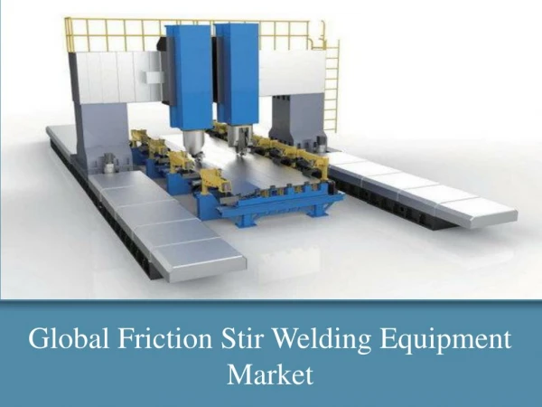
International Journal of Trend in Scientific Research and Development (IJTSRD) ISSN: 2456-6470 method enter the abode section wherever the rotating tool is allowed to dwell for a amount of your time, inflicting the temperature to extend any, up to its hot operating temperature. The warmth generated from resistance work is greatly smitten by the relative increase of contact extent still because the relative speed. This produces cyclic transient heat generation. The mock material is later to be cut away deed smart surface end. Fig 1.1 Structure of FSW Figure 1.2 Working Principle of FSW 1.1 Important Welding Parameters 1.1.2 Tool design The design of the tool is a critical factor as a good tool can improve both the quality of the repair and the maximum possible welding speed. It is desirable that the tool material is sufficiently strong, tough and hard wearing at the welding temperature. 1.1.1 Tool rotation and traverse speeds These two parameters have considerable importance and should be chosen with care to make sure a prominent and economical fastening cycle. The connection between the fastening speeds and also the heat input throughout fastening is complicated however generally; it will be aforesaid that increasing the motility speed or decreasing the traverse speed can lead to a warmer weld. so as to provide a prominent weld it's necessary that the fabric encompassing the tool is hot enough to modify the in depth plastic flow needed and minimize the forces performing on the tool. If the fabric is simply too cold then voids or different flaws could also be present within the stir zone and in extreme cases the tool could break. 1.1.3 Welding forces During welding a number of forces will act on the tool: A downwards force ,The traverse force, The lateral force one of the most important features of Friction stir process (FSP) is the utilization of readily available machines such as a milling machine, and using a simple inexpensive tool simple to conduct the process. For the experimentation of FSW vertical milling machine is used. In the vertical mill the spindle axis is @ IJTSRD | Available Online @ www.ijtsrd.com | Volume – 2 | Issue – 2 | Jan-Feb 2018 Page: 409
International Journal of Trend in Scientific Research and Development (IJTSRD) ISSN: 2456-6470 vertically oriented. Milling cutters are held in the spindle and rotate on its axis. The spindle can generally be extended allowing plunge cuts and drilling. There are two subcategories of vertical mills; (1) The Bed Mill and (2) Turret Mill. interface softens both components, and when they become plasticized the interface material is extruded out of the edges of the joint so that clean material from each component is left along the original interface. The relative motion is then stopped, and a higher final compressive force may be applied before the joint is allowed to cool down. The key to friction welding is that no molten material is generated, the weld being formed in the solid state. The friction heating is generating locally, so there is no widespread softening of the assembly. Some applications are: A.Shipbuilding and marine The shipbuilding and marine industries are two of the first industry sectors which have adopted the process for commercial applications. 4. STATEMENT OF PROBLEM B.Aerospace Friction stir welding is emerging technique for welding of aluminium alloys. The FSW process parameters such as tool shoulder diameter, tool pin diameter, tool rotation speed, welding speed and axial force play important role in deciding the weld quality. At present the aerospace industry is welding prototype and production parts by friction stir welding. Opportunities exist to weld skins to spars, ribs, and stringers for use in military and civilian aircraft. 5. METHODOLOGY C.Railway industry One of the foremost necessary options of Friction stir process (FSP) is that the utilization of immediately on the market machines like a miller, and employing a straightforward simple tool to conduct the task. For the experimentation of FSW vertical miller is employed. Within the vertical mill the spindle axis is vertically familiarized. Edge cutters are control within the spindle and rotate on its axis. The spindle will typically be extended permitting plunge cuts and drilling. There are two subcategories of vertical mills; (1) The Bed Mill and (2) Turret Mill. Friction stir processed ought to be clamped firmly before the process begin, therefore particularly designed grove backing plate and holding plates area unit accustomed hold the piece of work and keep it fastened throughout the process . Then a little hole with same diameter as pin is trained, rather than mistreatment the pin of the tool to start out penetrating the piece of work, this trained hole avoid an excessive amount of load on the tool for penetrating. Then the pin of the FSP tool is forced into the piece of work whereas it's rotating at the required motion speed, and therefore the shoulder become connected with the surface of the work piece. The rotating FSP tool is then transversal on the required direction with specific change of location speed. The commercial production of high speed trains made from aluminium extrusions which may be joined by friction stir welding has been published. D.Other industry sectors Electric motor housings (in production). Refrigeration panels. White goods. 2. NEED & IMPORTANCE OF RESEARCH The need of this work is to quantify the connection between axial force, spindle speed, travel speed, and alternative method parameters for friction stir welding (FSW) at high spindle speeds, and correlate the results with a finite part analysis model capable of predicting the forces and force throughout FSW. 3. OBJECTIVE To quantify the relationship between axial force, spindle speed, travel speed, and other process parameters for friction stir welding (FSW) at high spindle speeds, and correlate the results with a finite element analysis model capable of predicting the forces and torque during FSW. 5.1 Experimental Parameter Friction welding is carried out by moving one component relative to the other along a common interface, while applying a compressive force across the joint. The friction heating generated at the In this project mainly three parameters are taken for three different levels: @ IJTSRD | Available Online @ www.ijtsrd.com | Volume – 2 | Issue – 2 | Jan-Feb 2018 Page: 410
International Journal of Trend in Scientific Research and Development (IJTSRD) ISSN: 2456-6470 1. 2250 rpm The three parameters are as follow: 2. 2500 rpm 1. Tool geometry 3. 2750 rpm 2. Tool rotational speed 5.1.3 Traverse speed 3. Traverse speed Two tool speeds to be measured in friction stir welding in what way fast the tool rotates and how rapidly it traverses the line. So according to that tool rotational speed taken are 10, 15 & 20 mm/min, These parameters have significant reputation and must be chosen with care to ensure a successful and efficient welding cycle. 5.1.1 Tool Geometry For FSW experiment, it's needed to develop tool pure mathematics as per demand and style the tool pure mathematics in such the simplest way that the contact space between tool and base plate will increase for higher weld result. For better analysis of experiment THREE different types of geometrical tools made from H13 material are designed to study. 5.2 Experimental Responses Following responses are selected for study after the weld is performed they are as follow: 1. FSW tool with cylindrical pin 2. FSW tool with tapered pin 1. Ultimate welding tensile strength 3. FSW tool with square pin 5.2.1 Tensile test specimens 5.1.2 Tool rotational speed 1. From each joint, two tensile specimens were prepared as per the American Society of Mechanical Engineers (ASME IX) standards to evaluate the tensile strength of the joints. 2. Smooth tensile specimens were prepared to evaluate the tensile strength of the FSW joints were evaluated by conducting test on universal testing machine. Preparation of tensile test specimen and testing of the same were conducted In this experimentation, different spindle speeds are used. As the speed is varied the strength of the weld plate is also vary. As per machine specification THREE speeds for this experiment is selected and they are as per following. Fig 5.1 Dimensions of Specimen According to ASME Section– IX 5.2.2 Base Plate Material Now days the most frequently-used aluminum alloys for shipbuilding are Al6061 for plates for FSW. The main alloying element in the 6000 series is magnesium (mg) and silicon (si). A magnesium content of around 0.8 – 1.2% provides good strength with good formability and high corrosion resistance in sea water, which results in a hard enable alloy. AA is also of interest in many other applications, such as the aerospace industry, railway wagon sand in the brewing industry. The substrate materials chosen for the present project are Al 6061. Hence in the present work, experimental investigations are carried out to analyze the effect of friction stir welding process @ IJTSRD | Available Online @ www.ijtsrd.com | Volume – 2 | Issue – 2 | Jan-Feb 2018 Page: 411
International Journal of Trend in Scientific Research and Development (IJTSRD) ISSN: 2456-6470 parameters on the tensile strength of commercially available aluminum alloy Al6061. 5.3.1 Chemical Composition of H13 Carbon 0.32-0.45 We are using two Aluminium Alloys Which Alloys are as Follows:- AA6061 (150 x 180 x 6 mm) Chromium 4.75-5.5 Manganese 0.2-0.5 5.2.3 Chemical Composition of Al 6061 Molybdenum 1.1-1.75 Al = 95.8 – 98.6% Mg = 0.8 – 1.2% Cr = 0.04 – 0.35% Mn = Max 0.15% Phosphorus 0.03 max Cu = 0.15 – 0.4% Si = 0.4 – 0.8% Silicon 0.8-1.2 Fe = max 0.7% Sulphur 0.03 max Table 5.2 Chemical Composition of H13 5.3.2 Properties of H13 Tensile Strength Thermal Conductivity Modulus Of Elasticity GPa Density Hardness Kg/m3 HRC MPa W / m-k Figure 5.2 - Base Plate Al 6061 7750 49 1990 24.4 210 5.2.4 Mechanical Properties of Al 6061 Table 5.3 Properties of H13 Elongation(min) 12-17% 5.3.4 FSW tool and parameters Ultimate tensile strength 120 MPa Trial experiments were conducted to see the operating vary of the method parameter. possible limits of the parameters were chosen in such some way that the friction stir welded joints ought to be free from any visible external defects. 2.71 Kg/m3 Density Thermal conductivity 167 W/m-k Melting point 582-652 °C Hardness 105 HV Table 5.1 Properties of Al 6061 5.3 Tool Material Hot Work Tool Steel (H13) is used to welding the aluminium alloys. The chromium satisfied supports this alloy to resist softening if used at greater temperature. This alloy is wieldable. H13 catches applications for hot die work, die casting and extrusion dies. Machinability of the H13 is medium to good. Figure 5.3 - FSW tool with tapered, square & cylindrical pin @ IJTSRD | Available Online @ www.ijtsrd.com | Volume – 2 | Issue – 2 | Jan-Feb 2018 Page: 412
International Journal of Trend in Scientific Research and Development (IJTSRD) ISSN: 2456-6470 PARAMERERS LEVELS (-1) 0 (+1) LOW MEDIUM HIGH Tool rotational speed (rpm) 2250(P) 2500(Q) 2750(R) Tool feed rate (mm/min) 10(α) 15(β) 20(γ) Tool pin profile Cylindrical(C) Tapered(T) Square(S) Table 5.4 – Experimental parameters and coding The rolled plates of 6 mm thickness, Al 6061 aluminium alloy, were cut into the required size (180 mm x 150 mm) by power hacksaw cutting and milling. Square butt joint configuration was prepared to fabricate FSW joints. Figure 5.3 describes the detailed meaning of code. pure geometry into straightforward and little components, known as “finite elements”. These finite components area unit the building blocks of the finite part analysis. 5.4.2 Structural static analysis. The structural static analysis capabilities within the ABAQUS program area unit accustomed confirm the displacements, stresses, strains and forces that occur during a structure or element as results of applied loads. Static analysis is suitable for determination issues within which the time-dependent effects of inertia and damping don't considerably have an effect on the structure’s response. This analysis kind may be used for several applications, like crucial the strain intensities in fillets of mechanical parts or predicting the strain during a structure ensuing from a temperature distribution. For example: Aγ1, Bα1, cβ1, etc. . Figure 5.4 - FSW coding 5.4Focused experiments Trial tests accompanied on aluminum alloy 6061 plate conclude the working choice of the process constraint for the friction stir welding. Viable limits of the parameters were selected in such a way that the friction stir welded joints should be free from any evident outside faults. 5.5Design and FEA analysis The welded plate model is created by modelling in PROE software and it is imported in to the ABQUES Workbench software. As FEA is a computer based mathematically idealized real system, which breaks geometry into element. 5.4.1 Fundamental Concept of FEM The main rule that concerned in finite part technique is “DEVIDE and ANALYZE”. the best distinctive feature that separates finite part technique from different ways is “It divides the whole complicated In this step, we edit the material properties to the plate specimen. We specified the Young modulus and Poisson ratio to that specimen which is given in the figure. To apply the meshing to the geometric model @ IJTSRD | Available Online @ www.ijtsrd.com | Volume – 2 | Issue – 2 | Jan-Feb 2018 Page: 413
Fig 5.5 meshing to the geometric model It links a series of equation to each element and solves simultaneously to evaluate the behavior of the entire system. This tool is very useful for problem with complicated geometry, material properties and loading where exact and accurate analytical solution is difficult to obtain. 1.Meshing Discretizing of model into the small sections called as the element. Mesh element for this analysis was tetrahedron. To Apply Boundary Condition and Loading Condition. Fig 5.6 Boundary Condition for welded plate specimen After the applied boundary condition we apply the load over the plate to get stress phenomena. @ IJTSRD | Available Online @ www.ijtsrd.com | Volume – 2 | Issue – 2 | Jan-Feb 2018 Page: 414
International Journal of Trend in Scientific Research and Development (IJTSRD) ISSN: 2456-6470 Fig 5.7 Von misses stresses in Welded plate specimen Fig shows the equivalent von-Mises stress induced in welded plate specimen under the load of 17320 N load. The maximum stress is induced near the Centre of the welded plate specimen its maximum value is 105.4 MPa. Whereas experimentally, it is calculated as 131.8 MPa. Red zone indicates the area of maximum stress and blue zone indicates the area of minimum stress. 6. RESULT AND ANALYSIS Below table gives the result of all welded plate. Sr. No Tool Rotational Speed (rpm) Tool Travelling Speed (mm/min) Tool Shape Project Simulation Tensile strength (Mpa) 2250 10 Cylindrical 85 1 2250 20 Cylindrical 81.2 2 2500 15 Cylindrical 96.5 3 2750 10 Cylindrical 110.5 4 2750 15 Cylindrical 118.5 5 2750 20 Cylindrical 121.7 6 2250 10 Tapered 83.5 7 2250 15 Tapered 93.5 8 2500 15 Tapered 112.5 9 2500 20 Tapered 90.1 10 2750 10 Tapered 105.4 11 2750 15 Tapered 130.2 12 2250 10 Square 62.1 13 @ IJTSRD | Available Online @ www.ijtsrd.com | Volume – 2 | Issue – 2 | Jan-Feb 2018 Page: 415
International Journal of Trend in Scientific Research and Development (IJTSRD) ISSN: 2456 International Journal of Trend in Scientific Research and Development (IJTSRD) ISSN: 2456 International Journal of Trend in Scientific Research and Development (IJTSRD) ISSN: 2456-6470 2250 15 Square 82.4 14 2250 20 Square 94.2 15 2500 10 Square 62.9 16 2750 10 Square 99.2 17 2750 20 Square 110.7 110.7 18 Table. 6.1 Simulation Result Above simulation is taking for that welded plates whose working parameter are tool rotation 2750 10 mm transverse feed and tapered tool. 10 mm transverse feed and tapered tool. Above simulation is taking for that welded plates whose working parameter are tool rotation 2750 rpm, EFFECT OF TOOL FEED (mm/min) ON WELD TENSILE STRENGTH EFFECT OF TOOL FEED (mm/min) ON WELD TENSILE STRENGTH (MPa) FOR 2750 RPM (MPa) FOR 2750 RPM STRENGTH TENSILE (MPa) This plate gives the best ultimate tensile strength amongst the all 18 plates. This plate gives the best ultimate tensile strength 200 Cylindrical 0 2250 TOOL FEED (mm/min) TOOL FEED (mm/min) 2500 2750 Tapered Square Graph 6.3 - Effect of tool feed (mm/min) on weld tensile strength (MPa) for 2750 rpm tensile strength (MPa) for 2750 rpm Effect of tool feed (mm/min) on weld 7. CONCLUSION From the present experimental investigation the following conclusions are derived: Base metal AA 6061-H13 was found to exhibit the best characteristics for Friction Stir Welding. Tool material H13 found to withstand for AA 6061 base metal without tool breakage. As the tool transverse feed increased, UTS of FSW joint increases up to certain level and as feed is furthered increased, UTS decreases. As the tool rpm increases UTS of FSW joint increases as more heat is generated due to more friction. condition, tapered tool geometry gives the good UTS for joints the reason behind that is the increased contact area between tool and base plate. For the adopted experimental condition feed of 15 mm/min, geometry of tapered pin and tool rotatio 2750 rpm gives the good results of UTS of FSW joint. According to FEA, it is found that tool shape is the most significant parameter which affects the UTS of FSW joint. The effect of tool pin profile and process parameters on the appearance of and no obvious defect was found. and no obvious defect was found. From the present experimental investigation the following conclusions are derived: Base metal AA H13 was found to exhibit the best characteristics for Friction Stir Welding. Tool material H13 found to withstand for AA 6061 base metal without tool As the tool transverse feed increased, UTS of FSW joint increases up to certain level and as feed is furthered increased, UTS decreases. As the tool rpm increases UTS of FSW joint increases as more heat is generated due to more friction. For this experiment condition, tapered tool geometry gives the good UTS for joints the reason behind that is the increased contact area between tool and base plate. For the experimental condition feed of 15 mm/min, geometry of tapered pin and tool rotational speed of 2750 rpm gives the good results of UTS of FSW joint. According to FEA, it is found that tool shape is the most significant parameter which affects the UTS of The effect of tool pin profile and process parameters on the appearance of the weld is presented 6.1 Effect of Tool rpm on UTS Effect of Tool rpm on UTS EFFECT OF TOOL ROTATIONAL SPEED ON WELD TENSILE STRENGTH(MPa) FOR CONSTANT FEED OF 20 mm/min FEED OF 20 mm/min EFFECT OF TOOL ROTATIONAL SPEED ON WELD TENSILE STRENGTH(MPa) FOR CONSTANT STRENGTH TENSILE (MPa) 200 Cylindrical 0 2250 TOOL ROTATIONAL SPEED (rpm) TOOL ROTATIONAL SPEED (rpm) 2500 2750 Tapered Square Graph 6.2 - Effect of tool rpm on weld tensile strength (MPa) for constant feed of 20 mm/min strength (MPa) for constant feed of 20 mm/min Effect of tool rpm on weld tensile Graph 6.3 shows the effect of tool rotational speed on tensile strength. At lower rotational speed (2250 rpm) tensile strength of the FSW joints was lower. When the rotational speed was increased, correspondingly the tensile strength also increased and reaches maximum in range of 2500 to 2750 rpm. Maximum tensile strength obtain when the tool rotational speed reaches to 2750 rpm. 6.3 shows the effect of tool rotational speed on tensile strength. At lower rotational speed (2250 rpm) tensile strength of the FSW joints was lower. When the rotational speed was increased, correspondingly the tensile strength also increased and reaches a maximum in range of 2500 to 2750 rpm. Maximum tensile strength obtain when the tool rotational speed @ IJTSRD | Available Online @ www.ijtsrd.com @ IJTSRD | Available Online @ www.ijtsrd.com | Volume – 2 | Issue – 2 | Jan-Feb 2018 Feb 2018 Page: 416
International Journal of Trend in Scientific Research and Development (IJTSRD) ISSN: 2456-6470 7)Y. Rostamiyan , A. Seidanloo , H. Sohrabpoor , R. Teimouri, “Experimental studies on ultrasonically assisted friction stir AA6061”archives of civil and mechanical engineering 2015, pp.335-346. 8. REFERENCES 1)F.F. Wanga, W.Y. Lia,, J.J. Shenb, S.Y. Hub, J.L. Lia, J.F. dos Santosb, N. Huberb “Effect of tool rotational speed on the microstructure and mechanical properties of bobbin tool friction stir welding of Al-Li alloy” Institute of Materials Research, Materials Mechanics 2015. spot welding of 8)A.K. Lakshminarayanan, V.E. Annamalai, K. Elangovan, “Article Identification of optimum friction stir spot welding process parameters controlling the properties of low carbon automotive steel joints”in journal of material research and technology 2015, pp.1-11. 2)Yuan-Ching Lin, Jiun-Nan Chen “Influence of process parameters on friction stir spot welded aluminum joints by various threaded tools” Journal of Materials Processing Technology 2015, pp. 347–356. 9)Michael Besel, Yasuko Besel , Ulises Alfaro Mercado , Toshifumi Kakiuchi , Yoshihiko Uematsu on “Fatigue behaviour of friction stir welded Al–Mg–Sc alloy” in International Journal of Fatigue 2015, pp.1-11. 3)G. Rambabu , Balaji Naik , Venkata Rao , Srinivasa Rao , Madhusudan Reddy “Optimization of friction stir welding parameters for improved corrosion resistance of AA2219 aluminum alloy joints” Defence Technology 2015 pp. 1- 8. 10)Jian Luo , Wei Chen, Gen Fu, “Hybrid-heat effects on electrical-current aided friction stir welding of steel, and Al and Mg alloys”in Journal of Materials Processing Technology 2014, pp. 3002–3012. 4)Z.Shena, Y. Chen, M. Haghshenas , A.P. Gerlich “Role of welding parameters on interfacial bonding in dissimilar steel/aluminium friction stir welds” in Engineering Science and Technology an International Journal 2015, pp. 270-277. 11)J.F.Caseiro , R.A.F.Valente , A.Andrade-Campos , J.W.Yoon on “On the elasto-plastic buckling of Integrally Stiffened Panels (ISP) joined by Friction Stir Welding simulation and optimization algorithms” in International Journal of Mechanical Sciences 2013, pp.49-59. 5)Vijay Shivaji Gadakh, Kumar Adepu , “Heat generation model for taper cylindrical pin profile in FSW” Journal of Material Research and technology 2013, pp.370-375 (FSW): Numerical 6)J.Mohammadi , Y. Behnamian , A. Mostafaei , A.P. Gerlich “Tool geometry, rotation and travel speeds effects on the properties of dissimilar magnesium/aluminum friction stir welded lap joints” in Materials and Design 2015, pp.95–112. 12)G. Bussu 1, P.E. Irving “The role of residual stress and heat affected zone properties on Fatigue crack propagation in friction stir welded 2024-T351 aluminium joints” in International Journal of Fatigue 2003, pp.77–88. @ IJTSRD | Available Online @ www.ijtsrd.com | Volume – 2 | Issue – 2 | Jan-Feb 2018 Page: 417